Proceso híbrido de mecanizado de alta velocidad/mecanizado láser para la fabricación de moldes
Fundación Tekniker15/11/2006
Los fabricantes de moldes sufren cada vez mayores exigencias por parte del cliente final, en cuanto a calidad, precisión, y coste de la pieza final. Ello conlleva que estén continuamente buscando soluciones de mejora del proceso de fabricación. A su vez, los fabricantes de máquina herramienta están introduciendo nuevas tecnologías que permitan obtener máquinas híbridas, capaces de llevar a cabo operaciones de distinta índole en la misma máquina.
Aunque, las herramientas de corte actuales superan con creces las limitaciones que tenían hace unos años, pudiendo disponer fácilmente de herramientas de fresado de diámetros de hasta 0.5mm, las exigencias propias de las máquinas para dichas herramientas son muy altas. Además, puede que se produzcan desgastes y/o roturas de herramienta, o no se maximicen los ratios de producción.
El haz láser presenta la gran ventaja de ser una herramienta de trabajo sin contacto, de diámetro muy pequeño, que no sufre ni roturas, ni desgastes durante el proceso de mecanizado.
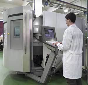
Al combinar las tecnologías del mecanizado y el láser en una misma máquina, se obtiene una máquina híbrida capacitada para llevar a cabo operaciones complementarias entre sí. La máquina DMU60L de Deckel Maho, disponible en Tekniker es un claro ejemplo de máquina híbrida fresado/láser.
En este artículo se recoge el estudio realizado en la búsqueda y obtención de los parámetros de proceso más adecuados del mecanizado láser. Se identifican dichos parámetros de proceso y se relacionan con los resultados. El estudio presentado es un estudio que se ha llevado a cabo específicamente para la máquina DMU60l.
Se planifica una amplia batería de experimentos, que tienen por objeto identificar los parámetros de proceso que presentan el mejor resultado en cuanto a acabado de pieza (menor rugosidad), y tiempo de mecanizado (menor tiempo de mecanizado).
Procedimiento Experimental
Equipamiento disponible
Cabezal de fresado a Alta Velocidad
Sistema Láser
El cabezal láser dispone de:
• Palpador: permite medir la profundidad mecanizada.
• Cámara de visión: permite la precisa colocación de la pieza.
• Escaner de espejos: crea un área de trabajo de aproximadamente 70mm2.
Cuando se requiere un área de trabajo mayor, la máquina realiza desplazamientos en sus ejes X-Y, según las necesidades del haz láser.
Se dispone de la opción de elegir el tamaño del diámetro del haz:
• Pequeño: 40ºm.
• Grande: 100ºm.
Software
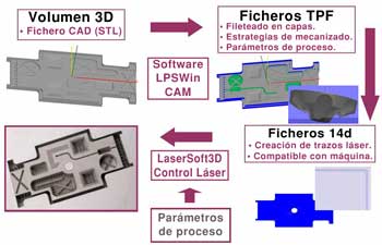
A su vez, los programas de mecanizado son creados mediante la aplicación LPSWin.
Dicha aplicación permite, tal y como se indica en la figura 2, partiendo de un fichero CAD (volumen 3D), crear ficheros “tpf” que contienen las estrategias de mecanizado y los parámetros de proceso asignados, todo ello por capas. Por último, se crean unos programas “l4d”, que crean trazos láser compatibles con la máquina.
Estudio del proceso
Material
La forma de las probetas es rectangular, con dimensiones 80x70x20 mm, que posibilitan su posterior caracterización en el microscopio electrónico de barrido (SEM) y en el microscopio confocal.
Procedimiento experimental
El procedimiento seguido en la realización de la experimentación consiste en la definición de unos parámetros de proceso iniciales, suministrados por el fabricante, que se van optimizando según los resultados obtenidos.
El objetivo es que los valores de rugosidad y tiempo de mecanizado sean tan pequeños como sea posible.
De entre todos los parámetros de proceso, se eligen como variables independientes a estudiar:
• Espesor de capa.
• Distancia entre haces.
• Velocidad del haz.
Se define un círculo de 5 mm de diámetro como forma geométrica a mecanizar.
Previamente al mecanizado del círculo, se lleva a cabo una búsqueda de tecnología, donde se ajustan los parámetros (frecuencia, intensidad, parámetro First Pulse Killer (FPK)) para el material objeto de estudio.
Analizando las tendencias, y resultados obtenidos, se han ido ajustando los parámetros hasta obtener valores de rugosidades adecuados.
En cuanto a la caracterización de las probetas, mediante un Perfilómetro sin contacto de la marca PLº se han obtenido imágenes confocales que permiten medir la rugosidad.
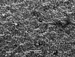
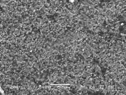
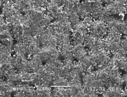
A su vez, mediante el microscopio electrónico de barrido JEOL JSM-5600LV, se han obtenido fotografías de la calidad superficial.
Resultados experimentales
Debido a que el objetivo inicialmente propuesto era mejorar la rugosida, al constatar que a diferente valor de profundidad de mecanizado, el valor de la rugosidad obtenida varía, la mayor parte de la experimentación se ha realizado con una profundidad de 0,2mm.
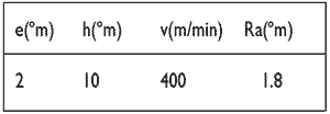
Los parámetros de proceso iniciales son los indicados por el fabricante de la máquina para un acero común, y figuran en la tabla 1.
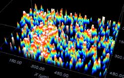

Después de una extensa experimentación, se consigue un conjunto de parámetros de proceso, con el que se obtiene una Ra de aproximadamente 1ºm. En la figura 5 se muestra una imagen correspondiente a este valor de rugosidad.
Se han obtenido diferentes grupos de parámetros de proceso que nos dan una rugosidad de aproximadamente 1ºm, habiendo entre ellos diferencia en cuanto al tiempo de mecanizado. El tiempo de mecanizado varía de 25 minutos a 42 minutos.
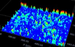
A su vez, el menor tiempo de mecanizado se consigue con una combinación de parámetros que presenta una rugosidad de aproximadamente 3,4ºm, que se muestra en la imagen de la figura 6.
En el caso del mecanizado en menor tiempo, se aprecian unos agujeros en la superficie mecanizada.
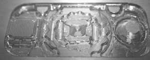
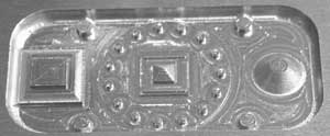
Mecanizado de Molde Ejemplo
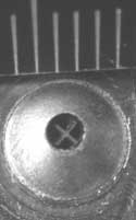
Parte del molde se mecaniza mediante herramienta de corte, realizándose una primera operación de desbaste, y una posterior de acabado. Se completa el mecanizado mediante el haz láser.
En las siguientes tablas y figuras se muestran las parámetros de proceso utilizados, y las imágenes del molde en diferentes fases de su fabricación.
Herramienta cilíndrica de metal duro de Ø2mm, con 4 filos de corte

Herramienta cilíndrica de metal duro de Ø 1 mm, con 2 filos de corte

Herramienta esférica de metal duro de Ø 1 mm, con 2 filos de corte

Conclusiones
La operación de fresado a alta velocidad consigue una tasa alta de arranque, mientras que el mecanizado láser permite la obtención de pequeñas figuras complejas.
De todas maneras, es necesario realizar un estudio de viabilidad por cada una de las piezas de interés, debido a que el láser es un proceso muy lento, y no es válido para el mecanizado de profundidades a partir de 5 mm.
Como conclusiones particulares del proceso que se obtienen, después de analizar las tendencias seguidas por los resultados en función de los parámetros de proceso, son:
Rugosidad
• A menor valor de distancia entre haces, menor es el valor de la rugosidad.
• La velocidad no influye mucho en el valor de la rugosidad.
• La rugosidad obtenida con el haz de mayor diámetro, es peor que con el diámetro pequeño.
• A menor profundidad de mecanizado, menor es la rugosidad.
Tiempo
• El tiempo de mecanizado es menor, cuando el espesor y la distancia entre haces es mayor.


