Sistemas para la adquisición de puntos en máquinas de medir por coordenadas
Traian Onaciu
Director Departamento Metrología
Fundació Ascamm Centre Tecnològic30/12/2001
Director Departamento Metrología
Fundació Ascamm Centre Tecnològic30/12/2001
En los procesos de control de calidad se manifiesta constantemente la necesidad de sistemas de evaluación más acertada de las características geométricas individuales o de subconjuntos de los productos industriales. Entre la diversidad de medios implicados en encontrar solución al problema mencionado, la MMC (Máquina de Medir por Coordenadas) es el medio más complejo y eficaz.
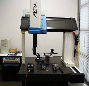
Fig. 1.- MMC actual – vista general
INTRODUCCIÓN
A finales del año1962, la firma italiana DEA construyó la primera máquina de medición en un garaje de Borgo San Paolo, cerca de Turín.
En 1973 Zeiss creó la máquina UMM500, equipada con un palpador universal, un ordenador y un control numérico (CN). En esta composición se encuentran por primera vez los dos elementos fundamentales que definen una maquina de medición tridimensional moderna: el palpador universal y el ordenador. El palpador universal es un captador de posición que, mediante contacto, permite localizar puntos sobre cualquier tipo de superficie.
Si bien en sus inicios la adquisición de puntos se realizaba únicamente por palpado, en la actualidad existen diversas soluciones para conseguir el mismo propósito. Denominaremos en lo que sigue sistema para la adquisición de puntos (SAP) al subconjunto de la máquina que se relaciona con la muestra a medir para localizar puntos sobre las superficies de interés.
El punto se considera como elemento geométrico fundamental, sin dimensión, sin propiedades físicas, como un “ladrillo” de todas las demás construcciones que realizará el software para identificar, localizar o relacionar entre si las características geométricas de la muestra sometida a análisis. La localización correcta de puntos sobre las superficies es un factor importante en la reducción del error sistemático de las MMC.
A lo largo de su breve historia la MMC ha empleado distintos sistemas de adquisición de puntos. Según la forma de relacionarse con la muestra se pueden dividir en dos grupos: SAP por contacto, llamados también palpadores , o SAP sin contacto. La MMC se puede ubicar para acceder a cualquier punto dentro de su campo de trabajo en forma de paralelepípedo. Continuadamente y en cada uno de los ejes de la máquina se leen las coordenadas (X,Y,Z), pero se validan sólo aquellos valores que corresponden a la posición en la cual el SAP está en una relación de incidencia con la superficie de interés. Este estado lo señala el usuario si se trata de palpadores pasivos, o un sensor integrado si es un SAP activo. Si el sistema es activo se puede leer la posición en movimiento, sin pérdida de precisión, mientras que en un sistema pasivo la lectura es necesariamente estática.
1. SAP POR CONTACTO
Se propone analizar la situación representada en la figura 2. En su desplazamiento a lo largo del eje X el palpador se aproxima a la cara plana de una pieza, orientada de forma perpendicular al eje. Como eventos en el tiempo, primero tiene lugar el contacto de la pieza con el palpador y, después, y como resultado de ese contacto, en los SAP activos cambia el estado el sensor acoplado al palpador.
Evaluar la abcisa A, como distancia a lo largo del eje X respeto al origen, supone la aplicación de la siguiente fórmula primitiva:
A = P – Va · Dt + k · r
donde:
- P es la posición leída en el regle del eje X
- Va es la velocidad de aproximación
- Dt es el tiempo entre el momento del contacto del palpador con la pieza y el disparo del sensor.
- k es el coeficiente del sentido de aproximación (k= 1 si se desplaza en X+; k=-1 si se desplaza en X-)
- r es el radio de la punta del palpador.
En un palpador pasivo la lectura es estática (Va = 0) y, por este motivo:
A = P + k · r
Si además se utiliza un palpador de punta viva (r = 0), entonces:
A = P
1.1 SAP pasivo de punta viva
Este tipo de SAP se utilizó en las primeras MMC, que no eran otra cosa que lectores de coordenadas de un puntero.
El único aspecto positivo de este tipo de palpador es su capacidad para localizar puntos reales sobre las superficies exploradas, debido al valor 0 del radio de su punta “viva”.
El uso exclusivamente manual lo hace poco productivo. Hay riesgo de daños de estilo en la zona palpada y posibilidad de error derivado de la alteración de la punta o de la superficie explorada.
Para la calibración de la punta se requiere un calibre cúbico, con orientación paralela a los ejes de la máquina. El origen del sistema de coordenadas esta basado en puntos palpados sobre el calibre. La orientación de la punta tiene que permitir el acceso a 3 caras adyacentes del calibre cúbico.
1.2 SAP activo de sensor digital
Su estructura corresponde al esquema siguiente: una punta esférica de rubí entra en contacto con el objeto a explorar. Esta punta, solidaria a un vástago metálico, se puede acoplar, si es necesario, mediante un alargo o, si no, directamente (enroscada) al sensor binario, capaz de ofrecer un cambio de estado de una señal eléctrica.
La fuerza graduable de un muelle obliga a los tres cilindros metálicos, orientados a 120º alrededor del eje del sistema, a que se mantengan tangentes a los tres pares de esferas, formando así un circuito eléctrico serie - normal cerrado. Cuando la punta entra en contacto con la superficie a explorar se abre uno de los 6 contactos eléctricos y la señal de salida cambia.
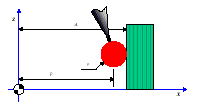
Fig. 2.- Palpando a lo largo del eje X
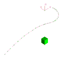
Fig.3.- Curva 3D interpolada por puntos digitalizados con punta “viva”
Es esta señal la que manda la lectura de los tres regles de la MMC y también activa los sistemas de freno para detener el movimiento de aproximación. Hablamos en este caso de un palpador dinámico, capaz de realizar adquisición de datos en movimiento. El programa gestiona las tres coordenadas del centro de la esfera en el momento del contacto con el objeto a medir. Este tipo de SAP es eficaz en medición de piezas cuya mayoría de sus características de interés están orientadas a lo largo de un eje, como en la figura 6.
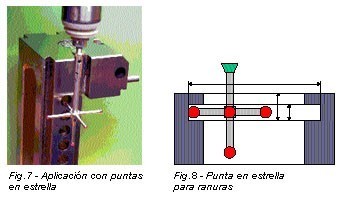
1.3 SAP con puntas en “estrella”
Cuando es preciso medir y localizar características con distintas orientaciones en 3D se puede utilizar una punta en estrella. Un sensor único se activa por el contacto con la pieza de cualquiera de las 5 puntas de rubí. Todas ellas tienen que estar habilitadas para medir mediante un proceso previo de calibración y calificación. En esta fase el programa evalúa para cada punta su radio dinámico y, para las puntas secundarias, evalúa las componentes axiales del vector de posición respecto a la punta principal. El valor numérico de estos vectores, con el signo que deriva de sus orientaciones, es utilizado por el programa para compensar la posición leída en los ejes.
Para calibrar y cualificar se utiliza un calibre esférico de incertidumbre certificada, de rango superior al conjunto de la MMC.
Durante el proceso de medición el usuario debe indicar al programa con cuál de las cinco puntas va a tocar, y prevenir la colisión de los demás elementos de la punta en estrella.
En aplicaciones para medir ranuras - como en la figura 8 - este tipo de punta es insustituible. Se pueden utilizar otras combinaciones de puntas conectadas a un mismo sensor en aplicaciones para medir engranajes.
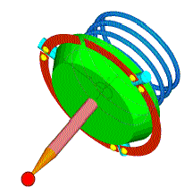
Fig. 4.- Esquema del principio básico de un sensor de contacto

Fig. 5.- Circuito serie- normal cerrado
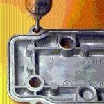
Fig. 6.- Palpador activo con sensor digital
1.4 SAP multiposición manual
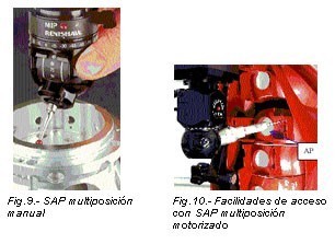
Si se desea evitar las interferencias con la muestra y realizar exploraciones desde posiciones distintas y a bajo coste se puede disponer de SAP con múltiples orientaciones de la punta.
Con dos giros en planos perpendiculares y contando con muy buena repetibilidad se puede calibrar y cualificar una multitud de posiciones discretas. En caso necesario, el operario cambia de posición el palpador de manera manual e informa al programa de medición cuál es la nueva posición en uso. Estas tareas pueden ralentizar el trabajo y precisan asistencia continua en ejecución de programas de medición de CN, que requieren el uso de distintas posiciones.
1.5 SAP multiposición motorizado
Similar al anterior, incluye en su estructura motores para los giros necesarios en el cambio de posición de la punta. Sus movimientos se pueden programar para la ejecución en CN. Dispone de protección contra la colisión.
En su estructura se pueden intercalar, además de alargadores de punta (AP), unos brazos alargadores que facilitan el acceso a zonas incómodas. La calibración y la calificación de puntas se ejecutan con programas de CN. Se pueden escoger posiciones preferentes entre las más de 670 posiciones disponibles. Para la medición compleja de piezas repetitivas, que supone el uso de varias puntas de medición, se puede optar por un sistema de cambio automático de puntas, que permite la automatización completa del proceso de medición.
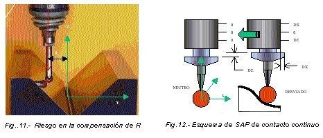
Observación: Al explorar puntos individuales utilizando SAP digitales, con la compensación de radio activada se comete un error geométrico sistemático si la aproximación hacia el punto deseado no se realiza a lo largo de la normal a la superficie en este punto. En la figura 11 se sitúa el SAP en Y = -k.
f = R*[SQRT(1-tan2(a) -1]
donde R es el radio de la punta y a es el ángulo entre la dirección de la exploración y la normal a la superficie en el punto de incidencia teórico. Se constata que el error f disminuye si se utilizan esferas pequeñas, o se anula cuando se explora a lo largo de la normal local a la superficie, cumpliendo a = 0.
2. SAP CONTACTO CONTINUO
La característica particular de estos SAP es la posibilidad de realizar la exploración en movimiento continuo con el palpador esférico, tangente a la superficie. Una controladora dedicada, con la ayuda del programa, genera las dos componentes de una fuerza que mantiene el sensor en un plano de exploración con desviaciones limitadas a un umbral preestablecido respeto a la posición neutra. En tiempo real se realiza la lectura de las coordenadas X,Y,Z en los regles de la máquina. A estos valores se aplican las correcciones con valor y signo igual a las pequeñas desviaciones de la esfera de exploración respeto a su posición neutra (con desviaciones nulas).
En el interior de este SAP las pequeñas desviaciones como las marcadas con DX y DZ se convierten en señal analógica mediante un sensor inductivo. Para facilidad de procesamiento, esta señal se convierte en formato digital. El programa realiza las correcciones de posición y genera un fichero nube de puntos situados todos en una superficie offset de la zona de interés, separada a una distancia equivalente al valor del radio de la punta del palpador implicado en el proceso de digitalizado. Estos puntos se pueden utilizar un sistema CAD para construir curvas y, mediante éstas, definir por zonas unos tramos de superficies para conseguir la versión informática del modelo explorado.
El monitor fotografiado en la figura 14 presenta la información de 6 canales de entrada de datos. A la izquierda de la imagen se observan las coordenadas leídas en los tres regles de la máquina y, al lado a la derecha, las desviaciones recogidas en el SAP de contacto continuo.
La ayuda de los SAP de contacto continuo es muy eficaz en los procesos de reingenieria de productos, que tiene como propósito conseguir rápidamente un modelo informático de superficies complejas, creadas por modelistas o estilistas.
Basados en estos modelos se pueden elaborar en poco tiempo los programas de control numérico para el proceso de mecanizado de la figura del molde, destinado a producir grandes series de estos productos.
3. SAP SIN CONTACTO
Los progresos realizados en el desarrollo de los sistemas de visión por ordenador y en el uso de los sistemas de láser industrial permiten explorar superficies 3D sin necesidad de palpar. En estos casos sobre la zona de interés incide el eje óptico del sistema o un haz láser.
3.1. SAP con sensor CCD para 2D
Un área CCD blanco/negro, un sistema de alumbrado y un sistema de lentes ópticas son los componentes principales de este SAP. La MMC transporta el sensor con el eje óptico orientado perpendicular a uno de los planos del sistema de referencia. La adquisición de puntos es confirmada por el operario en el momento en el que sitúa un cursor del sistema óptico encima del contorno de la pieza. El proceso se puede automatizar, función de la transición blanco/negro, ajustando el alumbrado y el umbral de sensibilidad del sistema.
Para obtener información de coordenadas 3D sobre una superficie se utiliza un haz láser con orientación inclinada respeto al eje óptico del sistema. La imagen del punto láser proyectado sobre la superficie se recibe en un sensor CCD lineal. Utilizando algoritmos de cálculo se pueden evaluar las tres coordenadas del punto de incidencia.
3.2. SAP láser vertical
En estos sistemas el haz láser tiene orientación vertical fija, incide sobre la superficie de interés, se refleja en ésta y retrocede a un sensor situado a un lado y otro del emisor. Relaciones geométricas en el triángulo: Emisor, Punto, Receptor permiten evaluar las coordenadas 3D. Estos sistemas, caracterizados por su elevada velocidad de exploración, ofrecen buenos resultados sólo en superficies suaves con acabado superficial uniforme, sin brillos y en zonas con la normal a la superficie próxima a la dirección vertical.
En la actualidad no existe un sistema bueno para todas las situaciones, y los diversos sistemas coexisten y se complementan
3.3. SAP láser + vídeo
En estos SAP un haz láser, un sistema óptico y un sistema de alumbrado se complementan para solucionar en parte la problemática del caso anterior. El haz láser es coaxial al eje del sistema óptico. La imagen del punto incidente sobre la superficie se focaliza mediante una lente especial de forma toroidal sobre un sensor de forma anular. La posición del punto diana está evaluada mediante un proceso de triangulación circular en el cual participan multitud de imágenes del mismo punto visto sobre segmentos de sensor, distribuidos alrededor.
Con este sensor se elimina el efecto de orientación del sensor respeto a la superficie. La velocidad de adquisición está limitada sólo por la velocidad de la línea de comunicación de datos. Acompañan al programa de usuario sistemas de procesado de imagen, que ayudan a identificar primitivas geométricas (círculos, rectángulos, radios de enlace).
El sistema de alumbrado con sus parámetros de trabajo se puede asociar al programa de exploración para tratar de la misma manera las muestras repetitivas.
4. TENDENCIAS
El desarrollo de los SAP proseguirá para dar mejores soluciones a la problemática compleja de la medición y digitalización.
En actualidad no existe un sistema bueno para todas las situaciones, y los diversos sistemas coexisten y se complementan. De los sistemas sin contacto se esperan mejoras en cuanto a la dependencia del brillo y el acabado superficial. Los sistemas por contacto se mantienen líderes en cuanto a la incertidumbre y repetibilidad. De los sistemas con láser se espera la capacidad de orientarse en 5 ejes en posición perpendicular a la superficie incidente.
Para digitalización rápida de modelos se están experimentando sistemas de adquisición de imágenes grabadas en una cámara vídeo con libertad de movimiento y orientación alrededor del modelo. La posición y la orientación de la cámara están relacionadas mediante un radiolocator con un punto fijo que sirve de origen. Patrones de sombra en forma de mallas se proyectan sobre la zona de interés. El programa actúa después de la adquisición, solapando imágenes en base a los patrones proyectados y reconstruyendo las formas 3D en base a las posiciones y las orientaciones, registradas en sincronismo con las imágenes grabadas. De este modo el proceso de adquisición de datos se puede reducir a segundos. Se prevé su aplicabilidad en la inspección de formas en tiempo real en líneas de fabricación, con capacidad de reconocimiento de la desviación de la forma prevista y exclusión de la muestra defectuosa.
más información:
http://www.metalunivers.com/arees/metrologiadimensional/tutorial/sistemasadquisicion.htm
3) METALUNIVERS Diciembre 2001
EMPRESAS O ENTIDADES RELACIONADAS
Ascamm
Hexagon Manufacturing Intelligence

