Design of an amortiguador active for the elimination of chatter in machine-tool
Mancisidor, J. De la Fuente, To. Neighbourhoods, J. Muñoa, IK4-Ideko, and R. Bárcena, department of Electronic Technology, University of the Basque Country (UPV/EHU), EUITI
12/12/2013In this work shows the electromagnetic actuator designed entirely in IK4-Ideko for the elimination of chatter in operations of mechanised. In addition to the design of the same, can observe the different essays of validation (temperature, linearity…) that have carried out in said actuator and the results of improvement that have obtained when entering it in a centre of mechanised.
1. Introduction
Nowadays, the vibrations autoexcitadas or chatter are ones of the most important restrictions of the processes of mechanised. These vibrations produce mainly because of the effect regenerativo [1][2] and are causantes of unacceptable superficial finishings, of breaks of tool and of the reduction of life of different mechanical elements. One of the most employed solutions to increase the margin of stability is probably the one to add an amortiguador passive sintonizado to the structure [3][4]. This technician is not new and has been widely used since it was proposed by Give Hartog [5]. However, the use of the shock-absorbers passive is not feasible in a lot of processes of mechanised where the dynamics of the system can vary during the process.
The active actuators can surpass part of these limitations with his capacity to adapt to some conditions cambiantes. These actuators basically produce a strength of reaction, controlled by means of an algorithm of control, on the main structure.
The development of active absorbers had his origin in the aeronautical sector component manufacturing sector component manufacturing industry. In a publication of 1968, Bies and Yang [6] showed that the problems that present the passive absorbers could solve adding an active element to the passive absorber. In 1970, Cowley and Boyle [7] proposed the use of an electromagnetic inertial actuator with an accelerometer to enter amortiguamiento active on the structure of a machine tool.
The combination of active devices and sensors form a solution mecatrónica advanced, whose behaviour is comparable to the one of an intelligent material like the piezoelectric actuators. In fact, the inertial actuators have better characteristic to improve the dynamic behaviour of the machines of big dimensions in operations of desbaste [8].
The piezoelectric actuators are used to to be planted on the machine in series, that is to say, are inside the flow of the strength and therefore, transmit strengths of cutting. This requires that the these actuators have a high rigidity. However, the inertial actuators are used to to be planted simultaneously, keeping like this the original rigidity of the structure [8][9]. The introduction of inertial actuators for machines of big desbastes has been studied by several authors in the last years. Ehmann And Nordmann [8], for example, recommended the introduction of inertial actuators in the machines-tool of big dimensions. Between the inertial actuators, stand out especially the electromagnetic, although also there have been applications where the hydraulics technology has been employed, like Brecher and Schulz [10], that developed an actuator electro-hydraulics to test different strategies of control for the elimination of chatter. The hydraulics technology is interesting because of the big strengths and travel that offer, but also presents big disadvantages like the problems of maintenance, no-linearity, and the delays that comport.
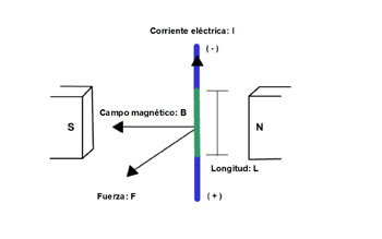
Regarding the electromagnetic actuators, has to mention that the energetic consumption will be greater on these that on the piezoelectric, since it has to surpass continuously the resistance of the same actuator, whereas the piezoelectric only need power to change his state. Even so, this greater consumption diminishes his importance because of the fact that the cost of the piezoelectric actuators can be until 3-4 greater times that an electromagnetic actuator. Besides, the electromagnetic actuators present the advantage that there is not physical contact between the mobile part and the fixed, what does that they are very used for applications of vibrations. Between the electromagnetic devices, the actuators of strength of reluctancia or strength of attraction offer big strengths, but this strength is proportional to the square of the speed and inversamente proportional to the square of the gap of air. This does that these actuators are difficult to control and are not usually used for applications of big precision. The actuators of strength of Lorentz, are able to generate lower strength, but the linearity that offer does that they are very used in the control of vibrations. In this case, the strength is proportional to the magnetic field, to the component of perpendicular speed to this field and to the load of the particle, by what when they use permanent magnets the strength is only proportional to the current applied (see Figure 1). In the literature have developed also several inertial actuators electro-magnetic that base in the strengths of Lorentz and that have served to delete chatter on machining centres [9][11].
In the last years, have developed and patented other actuators that combine so much the strengths of reluctancia like the strengths of Lorentz [12]. These actuators designated like MICA, offer a greater strength, but require a guided very precise. In this work, presents the development of a small active actuator based in the strengths of Lorentz, and that has been entirely designed in IK4-Ideko. In the section 2, describes the design of the actuator, that can divide in 5 parts: the requests, the magnetic design, the mechanical design, the design of the electronics equipment dealers equipment dealers of power and it final configuration. In the third section show the essays that have realizar to validate the actuator and finally summary the conclusions.
2. Design of the actuator
2.1. Requests
The design of the actuator is a task of big importance due to the fact that the actuators are used to to have his no-linearities and limitations that have to take in account to the hour of his dimensioning. The aim of this project has been the one to familiarise with different appearances in the design of actuators of this type. Thus, the actuator developed has been a device in a small way that it serve for machines-tool of no very big dimensions. Because of the importance that has the linearity of the actuator to apply some strategies of control or different filters, has procured build an able actuator to realizar like minimum 120 N of the most linear form possible. The bandwidth of frequencies has to be between the 20-90 Hz, due to the fact that the majority of the problems of structural vibrations are in this rank.
2.2. Magnetic design
The magnetic design has based in a variant of linear engine with a course limited. For this have manufactured two bobinados that will transport the sinusoidal current with the frequency wished. By means of the introduction of permanent magnets of neodymium (NdFeB) and thanks to the law of Lorentz, will generate a strength of linear trip on the mobile part of the actuator
The dimensioning of the magnets and of the bobinados has based in a calculation of magnetic finite elements (Flux), where has been able to calculate the theoretical strength obtenible with the design wished. In the Figure 2 can observe the model and the result of the magnetic flow on said model.
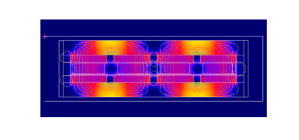
Appears 2. Model of magnetic finite elements by means of Flux.
2.3. Mechanical design
Apart from the magnetic design, is necessary to design properly the guided attendant to bear the magnetic strengths. This design earns importance due to the fact that the system of guided will be a posteriori the one who will endow of the necessary linearity to the actuator and the one who will determine the rigidity of the same. In this project, has designed a double flexo for said function. The flexos present like greater advantage the linearity, what does interesting his use in this type of applications. Besides, the fact that it was double does that the movement was totally linear, that is to say, vertically will not have any trip. This results interesting in this application, since this movement that occurs between the bobinado and the magnets has to be the possible minor.
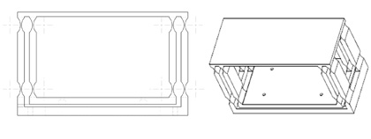
Appears 3. Design of the double flexo.
For dimensionar this flexo, have realizar two calculations by means of finite elements (I-deas). On the one hand, it has launched a calculation to check if the flexos will hold to fatigue the magnetic strengths generated. In addition to bearing the lower possible tension, has to have the sufficient rigidity so that the trip of the mobile part was not very high. On the other hand, it has realizar a dynamic calculation to predict the dynamic behaviour that will have the flexo. In this case, it interests that the way of suspension of the own flexo occur in a low frequency, so that it do not affect to the behaviour to the hour to realizar the active control. Therefore, to fulfil said aim have to have the lower possible rigidity, as long as it fulfil the calculated in the first calculation. Another option is the one to increase the mobile mass, but this mass has a space limited inside the actuator, by what the mobile mass also will have his maximum value. Finally after different models, has designed a flexo able to bear swings to fatigue and with a way of suspension that rondará the 18 Hz contemplating a mobile mass of some 7 kg. This frequency of the way of suspension finds very near of the rank wished and could affect partly to operation of the actuator when it act on machines with a frequency near in this way of suspension of the actuator. To solve this problem, it would be necessary to reduce the rigidity of the flexo, but this would comport a weakening to the hour to face the problem of the fatigue, and during the design of the flexo has seen that it is not viable. Therefore, the solution that goes to propose is the one of not changing the design of the flexo and attack this problem from the point of view of the control [11]. The actuator has of a placed accelerometer in the fixed part that will measure the vibration to reduce. To receive these signals, the actuator has of connectors in which it will be able to connect the wire with total ease. The signal of current also will be entered by means of a connector Harting.
2.4. Design of the electronics equipment dealers equipment dealers of power
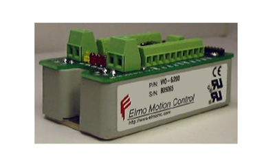
After developing the device, is necessary the cater it of power so that it can generate the sinusoidal signals and in this way obtain the strength of vibration. In the case of this actuator, has opted by the servo amplifier Elmo Violin of 0.95kW of power.
2.5. Configuration of the amortiguador active
Once designed all the parts of the actuator, the group forms the system mecatrónico able to reduce the vibrations on a structure. In the Figure 5 shows of schematic way the configuration of the system.
In him, can observe the actuator mounted in the ram of a centre of mechanised, with whose placed accelerometer in the fixed part measures the vibration in the point of location of the actuator. This signal is carried to the controller where will be converted to a digital signal and will be manipulated depending of the algorithm of control that go to employ in this controller. Once calculated the voltage to realizar, this is envoy to the amplifier where knowing the characteristics of the actuator will provide the necessary current to realizar the strength required. All this will realizar of continuous way with a frequency the sufficiently high so that there are not considerable delays in the performance.
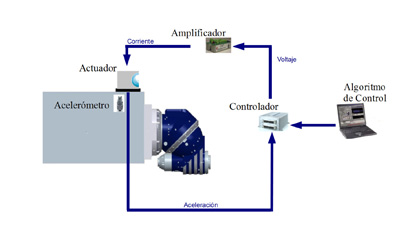
Appears 5. Configuration of the system mecatrónico.
3. Validation and characterisation
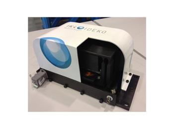
Once built the actuator (Figure 6), has checked his operation. The validation of the actuator has realizar by means of 4 essays. The first of them is the one to characterise the dynamics of the actuator and analyse the linearity that offers in function of the level of strength. The second treats to know the maximum level of strength that is able to offer the actuator. After these two validations, has realizar an essay to analyse the thermal sensors behaviour of the actuator. Finally, it has entered the actuator in a centre of mechanised to observe if it is able to delete cases of chatter.
3.1. Characterisation Forces/Voltage
To analyse this relation, puts a scanning of frequency with a constant value of voltage to the entrance of the servo amplifier of current and obtains the function of frequency response (FRF) between the strength obtained and the voltage of entrance. The measure of the strength has been realizar by means of a plate dinamométrica.
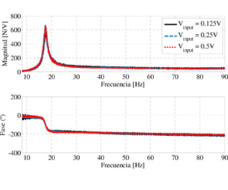
As it can observe in the Figure 7, the frequency of the way of suspension is in 17,6 Hz, validating like this the model of finite elements realizar. On the other hand, also it can see that the behaviour does not change with the level of strength by what can consider that the actuator has a linear behaviour, as it expected thanks to the flexo designed.
3.2 maximum Strength
To know the maximum strength that is able to realizar the actuator, have entered several levels of current in two different frequencies and has measured the strength by means of the plate dinamométrica. The result is reflected in the Table 1.
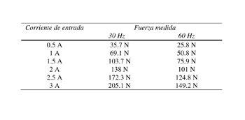
As it can observe , obtains sobradamente the strength wished for the two frequencies analysed. Even the real strength has surpassed the calculated theoretically by means of the software of electromagnetic analysis.
3.3 thermal sensors Analyses
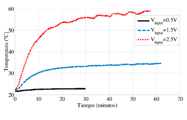
The thermal sensors is an important test to validate the actuator. Because of the resistance that offer the bobinados, these heat when a current is them entered. This warming can not reach high values due to the fact that from some values the permanent magnets lose faculties and can not obtain the same levels of strength. Besides, it exists the risk that to high temperatures can desmagnetizarse these permanent magnets and that the insulator of the bobinados resienta. In the case of this actuator, has planted the maximum temperature in the 100°C, so that it enters a margin of hygiene before going in in the zone where can appear the problems commented. In this essay, have testeado 3 different amplitudes of voltage of entrance and has analysed the evolution of the temperature in the bobinado by means of sensors of temperature. The voltage of entrance analysed carries a frequency of 60Hz. The results (Figure 8) show as from the hour begin to stabilise the temperatures and still find far of the temperature limit imposed. Thus, can give as validated his thermal sensors behaviour. Even so, always it is recommended to enter a system of refrigeration to the actuator.
3.4. Proofs of cut
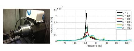
Like last step to validate the actuator, has to analyse if it is able to delete the chatter. For this, has planted the actuator in the ram of the prototype of centre of mechanised DS-630, as it can see in the Figure 9. The algorithm of control employed has been the Direct Velocity Feedback (DVF) by the fact that it is the one who better results has offered up to now in problems of vibrations of machine tool [13]. Before realizar the proofs of cut, has analysed by means of a hammer dinamométrico the answer that offers the machine as it increases the gain of the actuator. The result can be observed in the Figure 9. By means of this graphic can ensure that the operation of the actuator is correct since the main way of the system is reduced considerably. The increase more the gain can do that inestabilicen other ways.
Once seen the appropriate operation of the actuator and the necessary gains, has defined a process of cutting. The conditions of cutting and the tool are described in the Table 2. It treats of operations of planned in a vertical plane, cutting in steering X. In this way, they have realizar cuttings to 6 different heights And. As it has mentioned in the section 2.2, the way of suspension has been compensated by means of the control [11].

The Figure 10 sample the stability of the system for different values of And and depths of cutting. By reasons of confidentiality, have not been provided the absolute values in mm of depth of cutting and the values showed depend on a value b, whose value has been hid.
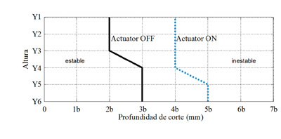
As it can observe , the capacity of cut has been bent for some heights, by what can see that although it treat of an actuator of little capacity of strength, also is able to improve the capacity of cutting.
4. Conclusions
In this work has been presented the electromagnetic inertial actuator developed entirely in Ideko-IK4. It has showed the magnetic design realizar to obtain a strength that finally has resulted to be greater that 140 N and has explained the design of a double complex flexo that serves to guide of form totally linear the mobile mass. In the validation of the actuator, has seen that the main way of suspension finds near of the rank of frequencies in which it wants to act , by what has posed the use of the control so that this way do not affect in the good operation of the actuator. On the other hand, it has showed the linearity achieved in the actuator, what facilitates the employment of different strategies or filters of control.
Has showed that the actuator térmicamente does not present any problem since it does not reach in any moment the agreed critical temperature. Even so, has to take in account that for back designs of actuators can be possible the have to design a system of refrigeration to be able to increase the amplitude of the current on the bobinados. Finally it has showed that although it treats of an actuator of little available strength, is able to increase the capacity of cut of a centre of mechanised. For this has planted the device in the ram and by means of an algorithm of control that realimenta the speed of vibration, has arrived to bend this capacity in some cases.
Gratitudes
This work has been realizar inside the project ER-2012/00019 PAINT (aeronautical sector component manufacturing sector component manufacturing sector component manufacturing Pole of Innovation in Turbines) funded by the Basque Government through his program Etorgai
References
[1] J. Tlusty, L. Spacek, Self-excited vibrations on machine tools, Nakl. CSAV (1954).
[2] S.Tobias, Machine-tool Vibration, Blackie. London, Glasgow (1965).
[3] N.D. Sims, To. Amarasinghe, K. Ridgway, Particle dampers for workpiece chatter migration, ASME International Mechanical Engineering Congress and Exposition (2005),
Orlando, USES, 825-832.
[4] And. Yang, J. Muñoa, And. Altintas, Optimization of multiple tuned mass dampers to supresses machine tool chatter, International Journal of Machine Tools & Manufacture 50(9)(2010), 834-842.
[5] J.P. Give Hartog, Mechanical vibrations, Dover, New York, 1985.
[6] D.To. Bies, T.M. Yang, Hybrid Vibration Isolation System For Helicopters”, Shock and
Vibration Bulletin (1968).
[7] To. Cowley, To. Boyle, Activate Dampers for Machine Tools, CIRP Annals 18(1)(1970),
213-222.
[8] C. Ehmann, R. Nordmann, Low Cost Actuator for Activate Damping of Large Machines, IFAC Conference on Mechatronic Systems (2002), Berkeley, USES.
[9] N. Loix, J.ph. Verschueren, Stand Alone Activate Damping Device, ACTUATOR 2004,
Bremen, Germany.
[10] C. Brecher, To. Schulz, Electrohydraulics Activate Damping System, CIRP Annals 54(1) (2005), 389-392.
[11] To. Bilbao, I. Azpeitia, S. Luyckx, N. Loix, J. Muñoa, Low Frequency Chatter Suppressesion using an Inertial Actuator, 9th CIRP International Conference on High Speed Machining (2012), Saint Sebastian, Spain.
[12] F. Claeyssen, G. Magnac, Or. Sosnicki, Moving Ironinging Controllable Actuators, ACTUATOR 2008, Bremen, Germany.
[13] J. Muñoa, I. Mancisidor, N. Loix, L.G. Uriarte, R. Barcena, M. Zatarain, Chatter suppressesion in ram type travelling column milling machines using to twinaxial inertial actuator, CIRP Annals – Manufacturing Technology (approved) (2013).


