Geometry compensation of coordinate measurement machines
Premise
Geometric errors
Bridge machines
Fundamental errors (parameters) which dealt with compensation algorithms are a total of 21 bridge machines: 9 errors of translation (6 of linearity, positioning 3), 9 errors of rotation and 3 errors in quadrature.


| LXX, Lyy, Lzz | Errors in positioning of the axes, due to the response of the ópti cas rules and the rotation of the axes. | Fig. 1A |
|---|---|---|
| Lxy Lxz LyX, Lyz LZX Lzy | Errors of linearity of the axes on the transverse axes. Due to the imperfect of the routes of displacement linearity and the effects of rotation of the axes. | Fig. 1A |
| Rxx, Rxy Rxz Ryx, Ryy Ryz Rzx, Rzy Rzz | Errors of rotation of the axes environment to each of the 3 axes. With the provisions of a vessel are called rool, pitch and jaw. Due to the imperfect of the routes of displacement linearity and structural deformations produced during the Assembly. | Fig. 1B |
| Qxy, Qyz, Qzx | Mistakes of balancing between pairs of axes. Due to the imperfections of assembling of the structure. | Fig. 1 c |
Gantry machines
Horizontal arm machines
The first parameter, called Rcx, takes into account the rigid rotation of the amount with respect to the longitudinal axis caused by the deformation of the structure to which is the amount (Fig.2).
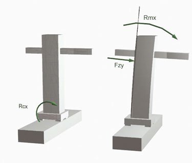
These 3 components of correction completed, for the horizontal arm machines, the model of compensation already described for vertical arm machines.
In the case of horizontal double arm machines are valid, separately, all the foregoing considerations. Errors due to the correlation of the two arms are offset in the management of the system of reference common to the two volumes of measurement.
Measurement errors and its compensation
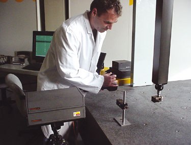
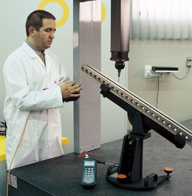
These operations are applied to the head of machine tools appropriate instruments which will make it possible to measure errors of rotation and translation of each of the axes. Each process is divided in steps, which depend on the type of machine and precision to fetch.
Then describes the main phases of compensation. At the end of each phase values obtained are entered into the map of compensation and accountability in order to correct the effect of these errors.
1st phase: Rotation errors
Electronic precision levels mounted on the head of the machine are used to measure rotation Rxx errors, Ryy. These values can be measured in differential form with respect to that obtained from other levels (reference levels) in the table.
An interferometric laser is used to measure the rest of rotation errors.
The relative rotation between the retroreflector (optical that, in this case is mounted on the machine head) and the Interferometer (reference optical) reads the laser through the different steps of compensation that are achieved through the shaft which is measuring.
As well as by the level of reference, including the optical reference will have to be solid with the Bureau of the pieces.
2nd phase: Roll of the Z axis error
This phase is sensitive and complex. This rotation cannot be measured with methods that we have already described.
The linearity is usually measured laser (this is described further below). The optical mounted on the head of the machine applies to jumps, something that can be more or less long. Thus, the differential reading between two measurements obtained with spacing (offset) appropriate optic will provide the values that are searched.
3rd phase: errors of linearity (linearity)
They are measured with Laser interferometric. Optical components which allow take transverse deviations mobile optical (mounted on the head of the machine) in compliance with respect to a reference optical during movements by the axis of measurement are used to detect them. The fixed optical (retroreflector) is usually located on the opposite side of the laser head.
4th phase: positioning errors and errors in quadrature
Positioning errors are normally detected the interferometric laser. Similarly to rotations, the retroreflector is mounted in the head of the machine and the Interferometer will be the optical reference. This is situated close to the laser head.
In the detection of errors in positioning phase, it is important to take into account the temperature of the optical rules, because of its thermal expansion. The procedure of compensation expected the temperature to which the machine made correct measurements is 20 ° c. When she is measuring positioning errors be counted the different temperatures of the optical rules and its coefficient of thermal expansion.
Quadrature errors are obtained from differential measurements of a caliber to be put in two positions for each of the 3 plans coordinated by the volume of measurement. The caliber is measured with a diagonal of the plane and then doing a diagonal opposite at the same level.
Verification of the formula of the uncertainty of measurement
Once completed the phase of correction of the Quadratures and activated the last part of the algorithm of set-off, are repeated measurements of the volumetric diagonals in the calibers of reference. Through these operations are verified the performance of the machine of measurement on the formula of expected measurement uncertainty.
Periodic verification of metrological system benefits
DEA recommends that measuring machines be checked and are repaired annually. Given the few mechanical needs of measuring machines, intervention is resolved in the most cases with a normal benefits verification, unless there are structural or functional variations which occurred during the use of the machine because of:
- Subsidence of the mechanical structure (improbable unless there are accidental collisions)
- Improper use of the machine
- Neglect of preventive peacekeeping operations
- Sinking of the pavement
- Effects of vibration caused by the environment (machines in operation, the passage of conveyor lanes, etc.). The machine is not well insulated.
- Use of the rollers of displacement when they are present
- Impairment of the benefits of the sensors or optical rules.
- The periodic calibration is a series of operations of maintenance and functional checks and metrological:
- Control of the State of the mechanical and structural bodies
- General conditions of operation of the machine verification
- Cleaning of travel guides
- Cleaning of optical rules
- Transmission belts tension
- Damage control and repair
- Verification of benefits metrological (see paragraph "Verification of the formula of uncertainty of measurement")
Only in the event of a significant difference with regard to the last check is the repair of the machine with the necessary instruments