This news article was originally written in Spanish. It has been automatically translated for your convenience. Reasonable efforts have been made to provide an accurate translation, however, no automated translation is perfect nor is it intended to replace a human translator. The original article in Spanish can be viewed at Sistemas para la adquisición de puntos en máquinas de medir por coordenadas
Systems for the acquisition of points on machines of measure for coordinates
Traian Onaciu
Metrology Department Director
Fundació Ascamm Centre Tecnològic30/12/2001
Metrology Department Director
Fundació Ascamm Centre Tecnològic30/12/2001
In the processes of quality control manifests constantly the need for systems of more accurate assessment of the individual geometric characteristics or subsets of industrial products. Among the diversity of the media involved in finding solution to the above problem, the MMC (machine of measure for coordinates) is the most complex and effective means.

Fig. 1.-Current MMC - overview
INTRODUCTION
At the end of the año1962, the Italian firm DEA built the first machine of measurement in a garage in Borgo San Paolo, close to Turin.
Zeiss created the UMM500 machine, equipped with a universal transducer, a computer and a numerical control (CN) in 1973. In this composition for the first time are the two fundamental elements that define a modern three-dimensional measuring machine: universal transducer and the computer. Universal transducer is a sampler of position, using contact, allows to locate points on any surface.
While in its early days the acquisition of points was only performed by probe, currently there are various solutions to achieve the same purpose. We will call in the following system for the acquisition of points (SAP) to the subset of the machine that relates to the sample to be measured to locate points on the surfaces of interest.
The point is considered as fundamental geometric element, no dimension, without physical properties, such as a "brick" of all the other constructions that will make the software to identify, locate, or link between if the geometric characteristics of the sample under analysis. The correct location of points on surfaces is an important factor in the reduction of the systematic error of the MMC.
Throughout its brief history the MMC has employed various systems of acquisition of points. According to the way interact with the sample can be divided into two groups: SAP by contact, called probes, or SAP without contact. The MMC can be located for access to any point within his field of work in the form of parallelepiped. Continuously and in each of the axes of the machine read the coordinates (X, Y, Z), but are validated only those values that correspond to the position in which the SAP is in a relationship of impact with the surface of interest. This State mentioned the user if it's passive probes, or an integrated sensor if it is an active SAP. If the system is active reads the position on movement, without loss of precision, while in a passive system reading is necessarily static.
1 SAP BY CONTACT
Intends to analyse the situation depicted in Figure 2. In their movement along the X axis the transducer is approaching the flat face of a piece, oriented perpendicular to the axis. As events in time, contact the piece with the transducer takes first place and then, and as a result of this contact, in the active SAP changes the status the sensor attached to the transducer.
Assess the abcisa A, as distance along the x-axis with respect to the origin, is the implementation of the primitive formula:
To = P Goes · Dt + k · r
where:
- P is the position read in the regle of the axis X
- Goes it is the speed of approximation
- Dt is the time between the moment of the contact of the palpador with the piece and the shot of the sensor.
- k it is the coefficient of the sense of approximation (k= 1 if it displaces in X+; k=-1 if it displaces in X-)
- r it is the radius of the tip of the palpador.
In a passive probe reading is static (Va = 0) and, for this reason:
To = P + k · r
If a transducer of the living art is also used (r = 0), then:
To = P
1.1. Passive SAP of living tip
This type of SAP was used in the first MMC, were not as anything other than a pointer coordinates readers.
The only positive of this type of transducer is its ability to locate real points of explored areas, due to the value 0 of the radius of its "living" tip.
The only manual use is bit productive. There is risk of damage of style in the palpada area and possibility of error arising from the alteration of the tip or the unexplored surface.
Cubic calibre, facing parallel to the axes of the machine is required for the calibration of the tip. The origin of the coordinate system is based on points devised on the caliber. The orientation of the tip must allow access to 3 adjacent faces of cubic caliber.
1.2. Active SAP of digital sensor
Its structure corresponds to the following scheme: a spherical Ruby tip comes into contact with the object to explore. This tip, solidarity to a metal stem, can be attached, if necessary, through a get or, if not, directly (wrapped) to the sensor binary, able to offer a change of an electrical signal.
Scalable from a spring force obliges the three metal cylinders, 120 ° about the axis of the system, to remain tangent to the three pairs of fields-oriented, thus forming an electric circuit series - normal closed. When the tip comes into contact with the surface to explore opens one of the six electrical contacts and the output signal changes.

Fig. 2 Touching along the X axis

Fig.3.-curve 3D interpolated points digitized with "viva" tip
This signal is that sends all three reading regles the MMC and also activates the brake systems to stop the movement of approximation. We speak here of a transducer dynamic, capable of performing data acquisition in movement. The program manages the three coordinates of the center of the sphere at the time of contact with the object to be measured. This type of SAP is effective in measuring of pieces whose most of its features of interest are oriented along an axis, as in Figure 6.
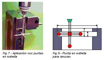
1.3 SAP with tips in "Star"
When it is necessary to measure and locate features with different orientations in 3D can be used a tip in Star. A single sensor is activated by contact with the piece of any of the 5 tips of Ruby. All of them have to be enabled to measure by a previous process of calibration and qualification. At this stage the program evaluates its RADIUS dynamic and, for the secondary tips to each end, evaluates the axial components of the vector's position on the main tip. The numeric value of these vectors, with the sign which is derived from its orientations, is used by the program to offset the position presented at the axes.
To calibrate and qualify using a spherical caliber of certified uncertainty, senior to the whole of the MMC.
During the measurement process the user must indicate to the program with which of the five points is going to play, and to prevent the collision of the other elements of the tip in Star.
In applications to measure slots - as in the figure 8 - this type of tip is insustituible. Can use other combinations of tips connected to a same sensor in applications to measure gears.

Fig. 4. Outline of the basic principle of a touch sensor

Fig. 5 CCTV series-normal

Fig. 6.- Palpador Active with digital sensor
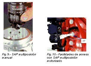
1.4 SAP multi-position manual
If you want to avoid interference with the sample and perform scans from different positions and at low cost is available from SAP with multiple orientations of the tip.
With two perpendicular planes twists and with very good repeatability you can calibrate and qualify a multitude of discrete positions. If necessary, the operator changes position transducer manually and informs the measurement program is the new position in use. These tasks can slow down the work and needed continued assistance in implementation of programmes of measurement of CN, which require the use of different positions.
1.5 SAP multi-position motorized
Similar to above, includes in its structure engines for the necessary turns on the change of position of the tip. Their movements can be scheduled for execution in CN. It has protection against collision.
Its structure is can insert, as well as extensions of punta (PA), alargadores arms to facilitate access to awkward areas. Calibration and qualification of tips run with programmes of CN. You can choose preferred positions among the more than 670 positions available. For complex measurement of repetitive pieces, which involves the use of several points of measurement, you can choose for a system of automatic change of ends, which allows the complete automation of the measurement process.
Observation: exploring individual points using SAP digital, with the compensation of checked radio will make a mistake geometric systematic if the approximation to the desired point is not performed during the normal to the surface at this point. In Figure 11 the SAP is situated in and = - k.
f = R*[SQRT(1-so2(to) -1]
Where R is the radius of the tip and to is the angle between the steering of the exploration and the normal to the surface in the point of theoretical incidence. It ascertains that the error f diminishes if they use small spheres, or cancels when it explores along the normal venue to the surface, fulfilling to = 0.
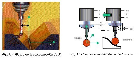
2 SAP CONTINUOUS CONTACT
The particular feature of these SAP is the possibility of carrying out exploration in continuous movement with the spherical, tangent probe to the surface. A dedicated controller, with the help of the program, generates the two components of a force that keeps the sensor at a level of exploration with deviations limited to a preset threshold respect to the neutral position. Real-time is the reading of the coordinates X, Y, Z in regles them machine. These values apply corrections with value and equal sign to small deviations from the field of exploration respect to its neutral position (with zero deviations).
In the interior of this SAP small deviations as the marked with DX and DZ are converted to analog signal through an inductive sensor. For ease of processing, this signal is converted into digital format. The program carries out position fixes and generates a file cloud of points located throughout a surface offset of the zone of interest, separate to a distance equivalent to the value of the radius of the tip of the probe involved in the process of digitizing. These points you can use a CAD system to build curves and, through them, define areas a few stretches of surfaces to get the computer version of the explored.
Monitor photographed in Figure 14 presents the information on 6 channels of data entry. To the left of the image there are read in all three coordinates regles machine and, next door to the right, the deviations contained in the SAP of continuous contact.
The help of the SAP of continuous contact is very effective in the process of reengineering of products, which aims to quickly achieve a computer model of complex surfaces, created by likenesses or stylists.
Based on these models is can develop in a short time programmes of numeric control for the process of machining of the figure of the mould, to produce large series of these products.
3 SAP WITHOUT CONTACT
The progress made in the development of vision systems by computer and in the use of industrial laser systems allow exploring 3D without having to touch surface. In these cases, the area of interest, it affects the optical axis of the system or a laser beam.
3.1 SAP with 2D CCD sensor
Area CCD black/white, a lighting system and a system of optical lenses are the major components of the SAP. The MMC carries the sensor with the optical axis oriented perpendicular to one of the planes of the reference system. The acquisition of points is confirmed by the operator at the time in which place a cursor in the optical system on top of the shape of the piece. The process can be automated, the transition function black/white, adjusting the lighting and the threshold of sensitivity of the system.
For information on coordinates 3D on a surface is used a beam laser with tilted orientation respect to the optical axis of the system. The image of the laser projected on the surface point is received in a linear CCD sensor. Using algorithms for calculating the three coordinates of the point of impact can be assessed.
3.2 SAP vertical laser
In these systems the laser beam has fixed vertical orientation, incident on the surface of interest, is reflected in it and back to a sensor located to one side and another of the issuer. Geometrical relationships in the triangle: sender, point, receiver evaluate the 3D coordinates. These systems, characterized by its high rate of exploration, offer good results only in smooth with a uniform surface finish, without glare surfaces and areas with the normal to the surface next to the vertical direction.
Currently there is not a good system for all situations, and different systems coexist and complement each other
3.3 SAP laser + video
These SAP a laser beam, an optical system and a system of lighting complement to partly solve the problem of the previous case. The laser beam are coaxial to the axis of the optical system. The image of the incident point on the surface is focused through a special lens form toroidal on a shape sensor override. The position of the target point is assessed through a process of circular triangulation which involved many images from the same point seen on segments of sensor, distributed around.
This sensor eliminates the effect of orientation of the sensor respect to the surface. The speed acquisition is only limited by the speed of the line of communication of information. They accompany the user program image processing systems, which help identify primitive geometric (circles, rectangles, radio link).
Lighting with its parameters of working system can be associated to the exploration program to treat in the same way the repeated samples.
4 TRENDS
The development of the SAP will continue to provide best solutions to the complex problems of measurement and digitization.
At present there is a good system for all situations, and different systems coexist and complement each other. Non-contact systems expected improvements in the dependence of brightness and surface finish. Contact systems are leaders in terms of the uncertainty and repeatability. Laser systems are expected to the ability to orient themselves in 5-axis perpendicular to the incident surface.
Acquisition of images recorded on a camera video with freedom of movement and orientation about the model is experiencing for rapid scanning of models. The position and orientation of the camera are related through a radiolocator with a fixed point of origin. Shadow in the form of mesh patterns are projected onto the area of interest. Programme acts after the acquisition, overlapping images on the basis of projected patterns and reconstructing Shapes 3D based on the positions and orientations, recorded in sync with the recorded images. In this way the data acquisition process cannot be reduced to seconds. Its applicability in the inspection of forms is expected in real time in production lines, with a capacity of recognition of the diversion of as intended and exclusion of the faulty sample.
More information:
3) METALUNIVERS December 2001
Related Companies or Entities
Eurecat (ex Fundació Privada Ascamm)
Hexagon Manufacturing Intelligence