Planning the process of machining from the extraction of information of mechanical design
José Montecinos r. Department of mechanical engineering and metallurgy (Catholic Chile P.Universidad), Jorge Machacuay. Department of mechanical engineering (Universidad de Piura), Claudio Fantozzi Department of mechanical engineering, Nuclear and production (University of Pisa), Massimo Granchi. Department of mechanical engineering, Nuclear and production (University of Pisa), Luciano Chiang S.. Department of mechanical engineering and metallurgy (Catholic P.Universidad of Chile)
15/03/2004The apparition of the modeladores solid 3D does more than a decade has allowed to incorporate in the archives of CAD information on the primitive geometrical that describe the solid. With the object to represent the solid models employ some structures of data that employ different methods, like CSG, B-Rep, etc The method CSG (Constructive Solid Geometry) employs a structure of database in shape of tree, in which the nodes leaves represent the primitive used to build the object, the nodes branches represent the operations of Boolean type and the node of root represents the solid object. This diagram of representation has attained apply, for example in [1], to generate a planificador of processes, by means of simulation of the cut in the process of milling frontal or milling lateral with the object to estimate the strengths of mechanised with base in the geometry of immersion of the tool when it finds the primitive individual used to build the solid.
However, exists a more recent method of modelación that is more efficient to incorporate no only geometrical information, but also information of level higher, that can be useful for the manufactura and that designates “feature-based design” or design in base to characteristic elements. The functionality of a modelador solid based in characteristic elements of design “features” is quite upper [2] to the traditional systems of modelación solid based in CSG or B-Rep, due to the fact that it incorporates information of greater level like topology, properties, etc., that that contained in the structure of geometrical data of the traditional systems.
The approach of characteristic elements or “features” can be very general because his definition can answer to the needs in each area of application. In design, these elements use to create and specify a model, whereas in planning of processes refer to forms and attributes associated to the processes, for example, the corresponding operations to objects eat: hole, box, slot, etc., in mechanised.
In this work proposes employ this approach of the elements “features” when designing a mechanical object in a modelador solid, with the object to develop a plan of manufacture for a station of work and, specifically in a centre of mechanised.
Application of the method of design on the basis of characteristic elements to generate a manufacturing plan
In order to facilitate the explanation of the procedure used to generate production plans are based on the following example of the piece shown in Figure 1.
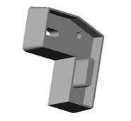
The “feature manager” of the program of the modelador solid presents a tree of the elements or “features” created in shape chronological used to build the piece showed in the figure. In this example, these find in the 1ª column of the Table 1.
Table 1. Characteristic elements of design and operations of manufacture
*Notice that the salient element projects on the upper plane of the model
The "manager feature" of the programme of the Modeler solid presents a tree of elements or "features" created in chronological form used to construct the piece shown in the figure. In this example, they are located in the first column of table 1.
The characteristic elements of design or "features" of the solid Modeler does not necessarily correspond to manufacturing operations required to define a manufacturing plan, given that the former do not consider the information in the order that the manufacturing operations would be made. Furthermore, machining operations to be only of subtracting type, i.e., elimination of material, do not include additive type which would be the case of the "feature" outgoing extraction of solid Modeler, which was created before the last item: "start angle". Therefore it would be desirable to build a table of correspondence, which is the proposed in table 1.
Table 1, proposes an operational plan to make the piece in a machining center. Of course that this would not be the only plan, since it could generate other different plans through other possible operations. The important thing here is that the information necessary to develop each operation can be extracted from the elements or "features" of design of the model, which turn to indicate in the penultimate column of the table. Those elements appear in the column next to the column of operations or "features" that provide the information necessary to plan an operation in particular and in the last column indicates the reference point from which was built the "feature" of design...
The difference between an operation of roughing and finishing is that probably would have a change of tool and cutting conditions and, in addition, the first machines whereas one about measurement of material on the heights of the pieceon the other hand the latter considered the piece with the final levels.
Construction of a manufacturing plan

Integration of CAD - CAPP
C++ which can call the functions of API interface for SolidWorks, allowing access to the functionality of the software was used to develop the program. Using the functions of the libraries are implemented methods or functions to initiate, terminate an application, manage events, etc. corresponding to the application built as a dll. This is installed in the SolidWorks menu after adding it in the option "add-in" plug-ins, as shown in Figure 4.
In this menu are options, one of which displays a table with the characteristic "features" elements of design of the piece, similar to table 1 of the example, except that the column of operations must be completed either by means of a procedure for the recognition of "features" or but manually as in this case. In this way you can, by way of trial, prepare a plan of operations with the view of the piece, all within the design environment.
Extracted the relevant information from the "feature" and that contained in the underlying elements or "subfeatures", as for example the points that make up the sketches or "sketch" with the corresponding methods of the API. The purpose is to use it to generate tool trajectories and thereby produce the production plan.
Conclusion
References
[1] Cho, H., "A formal approach to integrating computer aided process planning and shop floor control", ASME, j. Eng for Industry, Vol116, feb. 1994, p.108-116.
[2] Nau, D.S., Herrmann, J.W., Regli, W.C., "Design classification and hybrid variant-generative process planning", University of Maryland, 1997
[3] R.Tuttle, g. Little, j. Corney, Clark, D.E.R., "Feature recognition for NC programming part", Dep. of Mechanical Engineering, Heriot-Watt Univ., Edinburgh, UK 1997, (disp) online
[4] 2001API SolidWorks, Release Notes


