Measurement systems integrated in processes of grinding machine
These signals are used to change the progress of the grinding process and determine when the piece to reached the dimension scheduled stopping the advance of the grinding wheel and finishing grinding. This type of measurement we will call her in-process.
Once the process of production, depending on the existing quality assurance procedures, the produced pieces are measured in external measurement equipment to check that these meet the requirements of accuracy required. The parameters which are frequently check are the roundness, cylindricity, cone, surface roughness, etc. These measuring devices emit certain reports of the measurements made. This type of measurement we will call her with post-processing.
Current manufacturers of CNC's are betting more and more by the so-called open controls, which basically take advantage of the PC architecture to allow the user to implement own functions, making available many remedies of the control. This type of architecture of CNC's makes possible the development of integrated with the own CNC measurement systems, which allow you to include in the machine in-process and post-processing measurement functionality without having to resort to external equipment.
In addition there are certain processes of grinding whose measurement can not be satisfied with the use of commercial equipment and therefore require the development of solutions specific to the measurement. In this article will present two developments of gauges for grinding processes which will use the architecture of open controls for its implementation, specifically a meter multidiámetros and a meter of blade tips for high speed grinding process. Initially are the basis for the integration of measurement systems in machines.
The integration of functions for measuring post-proces in the machine makes it also a measurement machine and, therefore, in addition to machining functions as such, has to endure the functions of measurement such as storage of results, generation of reports and impressions, etc. It is essential to provide these systems of calibration systems that enable traceability of measurements according to the national and international standards.
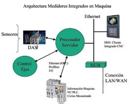
Architecture of an integrated measurement system
- Sensors: Are responsible for converting the physical magnitude, in our case a dimension, an electrical magnitude. For grinding the technique most used is that of dimensional measurement by contact linear encoder (LVDT), mainly for his immunity in the operation with coolant. Measurement by contact presents limitations for operation at high speed, so it is often used non-contact sensors (triangulation, fiber optic laser, flows induced, capacitive, etc.).
The most common interface of sensors is the willingness of an analogue signal proportional to the magnitude to measure. In some cases they have also signals compatible with encoders (TTL, 1VPP, etc.).
- DAS: (Data Acquisition System). It is a system that allows to acquire (digitize) the information from one or more sensors. The data acquisition system requirements vary depending on the type of sensor used and the necessary frequency response.
- Control axes positioning: The sensors have to be placed at appropriate points to capture the required information. The meter must be able to command the axes of positioning of the sensors. The requirements of accuracy of these axes are high and are often used very precisely measuring systems (< 0,1 µm). Control of positioning of these axes can be integrated into the processor of the meter, or you can command from the CNC of the machine.
- Processor: this is the unit responsible for collecting and analyzing the information from different sensors and processing. It also has to be able to act on the machining. To this end it is necessary that this processor available channels of communication with the controller of the machine. These channels are also needed as input channels of information, as it not only processor has to evaluate the information from the sensors, but need information on the process of machining that is contained in the CNC/PLC, as for example the process parameters (rpm, progress, positions of the axes, etc.), operations of measure, etc.
Depending on the required processing you can choose to integrate the processing on the processor of the machine (open CNC) either opt for a stand-alone processor with communication with the CNC/PLC if required much capacity calculation and processing.
Channels of communication (interface) with the machine (CNC/PLC).
The communication interfaces used with the machine are the following:
- Digital inputs/outputs: are the simplest. A set of digital signals allow exchange of information with other devices. They are the most commonly used in commercial meters, but greatly limited the amount of information to Exchange.
- Field buses. The connection of the meter to the fieldbus of the CNC/PLC is a possibility of exchange of information between the meter and controller of the machine. PROFIBUS is the choice but more advisable in this type of communication than this supported by two major manufacturers of CNC´S Siemens and Fanuc. Through this type of bus is accessed PLC information so if you require information in le CNC is necessary to pass such information to the a.6 of the PLC.
- Ethernet. It is more usual for the CNC to have this type of interfaces for Exchange of information with the CNC/PLC. Both temples and Fanuc have this possibility, and the development of libraries of communication allows the exchange of information with the machine. Using this type of communication is accessible to virtually all of the information contained in it the machine (CNC/PLC) controller. OPC (Ole Process Control) is a technique of programming that is asserting itself as exchange of information with the CNC/PLC.
- In the case of experienced meters it has opted for a combination of wired Ethernet and I/O. The wired I/O are used because of rapid communication and wired security requirement.
- HMI (Human Machine Interface): Management and programming environment must be integrated in the CNC. So the solution adopted has been that of distributed software. A client architecture allows the client (HMI) to request any kind of information and commands to the server (processor). These applications client can operate in a single processor (PC) or processor independent. A local network between server and client connection facilitates the exchange of information. This type of architecture facilitates that the clients can run on any connected PC network to the server.
- Integration of customer networks: via Ethernet allows to integrate the meter on a local (Area Network Lan) network or wide area (Word Area Network) network.This type of connection provides that the results of the measurements can be stored and evaluated in (PCs) devices connected to the network. Integration into a wide area (WAN) network is important for maintaining remote facilitating the Teleservice.

Meter of the tips of the blades
The high speed grinders are the method currently used and carry out this process at speeds close to the operation of the engine, making the measurement of the fan blades similar to the flight conditions (up to 6000 RPM). This is a very important factor, and that the fan blades are not fixed, and therefore the centripetal force caused during the rotation of the compressor at high speed causes that they are in a position similar to the operation.
It is obvious that the commercial gauges that used the techniques of measurement by contact are not suitable for working with discontinuous pieces at high speed. Why a sensor to which we will call TOD (optical displacement transducer) has been developed for this type of measurement and has developed a meter integrated in the grinding machine following the architecture described above.
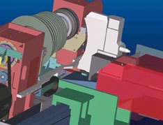
The designed system has architecture shown in Figure 3.2.
- A head of measurement or sensor containing a TOD (optical displacement transducer) of own manufacture.
- One/two shafts which positioned the head of measurement at the measuring point.
- An incremental encoder to read the angular position of the rotor during grinding and thus synchronize the measurement of each blade.
- A processor for the acquisition and treatment of the signals generated by the head of measurement. This system provides all the necessary interface with the drivers of the grinding process.
As shown in the figure the DAN BTM is mounted on the grinding machine, as opposed to the grinding wheel. To the grinding process produces variation in the size of the fan blades, measuring system provides in real time the extent of the fan blades and interacts with the driver of the grinding machine.

Using this optic displacement transducer, the DAN BTM Model determines the radius of the blade of the compressor by measuring the arc of the blade while touring. As shown in Figure 3.3, placed a source of collimated light (infrared diode) on one side, by placing an optical transducer (camera) on the opposite side. A lens and a system of mirrors capture the image of the tip of the blade and project on photocathode of converter image or photomultiplier tube which is very fast with bandwidth of 1 MHZ transducer. While the blade rotates through the light source, generate a black/white flank (or shadow) in the transducer. By measuring the maximum length of the wing, represented by the height of the arc of the blade, determines the RADIUS. The TOD is the radius of each of the blades, generating an analogue signal proportional to the displacement of the edge or blade RADIUS (see Figure 3.4).
The analog signal is analysed by a system of data acquisition, and by processing the signal in combination with the angular position of the rotor determined with an encoder estimates the radius of each blade.

System measurement. Software acquisition and analysis
The meter has optimised signal processing, with implementation of filters for elimination of electrical noise, analysis of 1 or more laps with calculations of the average or median of each blade and curves of linearization of signals. The previous commercial systems only processed the signal of a return. The power of calculation that you have a PC dedicated to the measurement allows to process information of several laps, averaging results for each of the blades and removing the wrong measures. Tests using this algorithm produced better results for repeatability to be more immune to electrical interference in the signal to be measured. Repetibilidades has been made of<0,003 mm frente a las 0,016 mm obtenidas sin la aplicación de los algoritmos optimizados. mm="" frente="" a="" las="" 0,016="" mm="" obtenidas="" sin="" la="" aplicación="" de="" los="" algoritmos="">


Meter multidiámetros
It's an absolute meter to enable measurement in process integrated with the CNC of the machine. The possibility of post-processing of roundness, cylindricity, Cone and profile measurements, as well as have made measurements analysis software are also available.
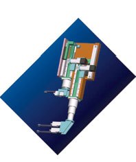
Commercial meters have limited ranges of measurement and do not allow meter large diameters. Any diameter between 50-300 mm can be measured with this type of meter, and the measurement of multiple diameters in the same piece can be programmed.
The figure shows the type of meter. Two motorized and numerically controlled by the meter arm positioned a contact in the area of measurement transducers. Depending on the diameter measuring measurement system calculates the position of the arms, and processes the information of the probes to obtain the dimensions of the piece.
Integration with CNC allows measurement system to know at all times the position of rotation of the piece and the position of the table, obtaining forms and profiles of the pieces.
The resolution of the system is< 0,1="" µm="" y="" la="" precisión="" de="" ±2µm="" en="" todo="" el="" rango="" de="">
The management of meter, the programming cycles of measurement, reporting of measurement this fully integrated with the CNC of the machine.
Also provides printing of reports, thus cone the connection in LAN, WAN network storage measures or analysis of the measurements in other PCs connected with the CNC.

Conclusions
Development of measurement systems integrated into machines entails the dominance of certain technologies such as:
- Knowledge of the machine and machining processes.
- Knowledge of sensors and its application. Sensors business, doing the work of the engineering of measurement may be used in the majority of cases, or processing of the signals supplied by the sensors and other more complex cases will require the design of the sensor itself.
- Knowledge of signal processing.
- Knowledge of open CNC architecture and programming techniques.
- Industrial communications.
The manufacturers of the machines as well as the technical mastery in these areas, should evaluate the cost of the development of proprietary measurement systems integrated in the CNC, with the use of commercial systems. Once the project the unit cost is reduced with which there are more likely to incorporate new features in machines with a minor increase in costs. The number of units to produce in order to amortize the development of the product is essential to make implementation decisions.

On the other hand developed the Server/client architecture and high-speed communication interfaces allow total integration with the driver of the process of grinding, even with the possibility that both systems operate in the same processor. This allows an exchange of information in real time between process of machining and meter, being able to adapt the process based on the information provided by the meter. All this coupled with the development of graphic representations in a Windows environment and friendly operator interfaces provide a current and easy to use, compared to the commercial proprietary systems software that everyone uses different interfaces.
Another kind of measurements by the inclusion of new sensors, can be integrated as well as the dimensional verification of produced parts, such as:
- Surface quality of the piece.
- Hardness of the material.
- Detection of fissure and cracking.
- Characterization of tools (toothache).
- Imbalance of grinding wheel, cutting of air GAP).
All these measurements are integrated on the same computer without the need to incorporate instrumentation and different manufacturers of measurement equipment operator panels. This facilitates the work of the operator of the machine with a single management environment in a friendly language.
The application of new technologies in miniaturization of sensors and the use of sensors wireless (wireless) with self-generation of energy (self energised) would enhance the possibilities for the integration of measuring on the machine. n