Recent advances in rapid manufacturing and laser surface treatment processes
The cleaning is another interesting application of laser technology. The latest developments are focused on cleaning of electronic devices, where it is necessary to eliminate weldable lacquers, pollution, polymeric residues and the surface oxide layers. For this reason, radiation laser pulsed with pulses of 10 to 250 ns in duration is used. Due to the high intensity and short interval of interaction, non-metallic coatings evaporate, while the metal surface of the substrate remains intact.
The polished surface is a new field of application to lasers. In this process, surface roughness, caused for example after a process of milling or deburring, alisan through the fusion of a thin layer of material. The speed of this process is usually between 0.2 and 5 cm2/min. This technique could be applied to grinding of injection and casting moulds and medical instruments.
The process of selective fading by laser (SLM) can be used for the direct manufacture of pieces of metal from materials in series. Thanks to a full cast of the material in powder form, you can get densities close to 100 per cent, with good mechanical properties. The materials which are being investigated are stainless steel 1.4404, the tool 1.2343 steel and titanium TiA16V4. The use of the SLM technique offers advantages in certain processes. The manufacture of functional prototypes from materials in series saves time compared to conventional processes, as the cast. Another example of these advantages is the use of the SLM process for the production of small batches in series or individual parts (e.g., implants doctors), with great flexibility and possibility to replace other conventional processes.
Coating by laser
Make laser
Powder injection nozzle
Powder flow
Base piece
Weld bath
Layer of coating
Dilution area
Heat affected zone
Scanning direction


Slit size: size of the slit
continuous coaxial powder injection with different sizes of slit
Concepts on powder injection
In the coating by laser, the supply of input materials is one of the most important factors for the control of the process. However, teams that exist currently in the market are designed to meet the needs of the research centres and, therefore, it is necessary to continue to work to create computers that conform to the requirements of the industry in terms of reliabilitymaintenance and useful life. There are three techniques of injection of powder:
Injection outside the shaft (a single stream of powder is injected side so the beam laser, Figure 1)
Continuous coaxial injection (injected a flow of tapered powder that covers the beam laser, Figure 2)
coaxial nyección discontinuous (inject three or more flows of dust in coaxial connection to the beam, Figure 3).
The injection of dust out of the axis is suitable for wide tracks covering. In the case of tracks with a width of 0.5 to 5 mm, use a slit with circular cross-section with a diameter of between 1.5 and 3.5 mm. For wider tracks (5-25 mm), use a slit with rectangular cross section (e.g. 15 x 1.5 mm2). Outside the axis injection technique can also be used for covering areas of difficult access. However, in injection outside of the axis, the nozzle is placed in lateral position the laser beam, and therefore, is not a technique for three-dimensional coating.
A flow of tapered powder that covers the laser beam is used in the case of the continuous coaxial injection. The flow of dust is characterized by the following factors: diameter at the focal point of the flow of powder (dp) and distance between the nozzle and the focal point (fp) (Figure 4). In turn, these parameters depend on the size of the nozzle, the carrier gas flow, the flow of dust and the size of dust particles. As shown in Figure 5, with a larger mouthpiece, the diameter of the focal point increases. The same applies if the flow of dust increases. Furthermore, the reduction in the size of the particles causes a decrease in the focal diameter of the flow. The focal diameter of the flow of dust in the continuous coaxial injection is usually fall between 1 and 3 mm.
The main advantage that presents continuous coaxial injection with injection outside the axis is that it can be used in three-dimensional coating. However, the inclination of the mouthpiece is limited. Given that the homogeneity of the cone of dust depends on the distribution of the dust within the expansion of the nozzle Chamber, when the mouthpiece is bent, the flow will be affected by gravity. Found that the angle of inclination maximum, while the geometry of the coating is significantly affected, is 20 °.
In the case of discontinuous coaxial injection, three or more powder flows are distributed around the laser beam to form the focal point of the flow (Figure 3). The focal point in these cases usually present a diameter between 2.5 and 4 mm. The main advantage of the discontinuous coaxial injection is that you can use for lining work in three dimensions and any-angle of nozzle. Figure 5 shows a flow of vertical powder and a flow with a tilt of 45 °. The focal point is barely affected by the inclination. In fact, mouthpieces which allow to use an angle of 180 ° (reverse coating) are proven.


Fig. 7: Coating of the surface of a cylinder of the engine of a motorcycle by rolling an optical cavity with integrated injection unit; material base and material contribution: AlSi alloy
Applications of laser cladding
The technique of laser cladding can be used potentially in the repair of bearings of crankshafts of great size (trucks and ships, large engines for power plants). Figure 4 shows the lining of the bearings of the crankshaft of a truck. In order to perform the lining of the edges of the pad, it is necessary to use a narrow injection nozzle, so in this case you cannot use a system of coaxial injection.
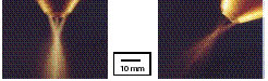
Coaxial injection is used, for example, in the aerospace sector to refurbish some parts of turbine engines, as the boards or the ends of the blades. Since in the majority of these cases the track to take is small, the best technique is coaxial injection, given the size of the focal point of the flow. Figure 5 shows the lining of the end of a TiA16V4 blade on a smooth substrate. In addition, the oxidation of the piece (Figure 6) can minimize through an additional coating. Although the three types of powder injection can be used for different applications, special work require special solutions. An example of "task" would be an inner surface coating. When the diameter of the slit must be less than about 300 mm, you can use any of the three techniques described. In this case, use a special optical cavity with integrated injection unit. Figure 7 shows the lining of the surface of a cylinder of the engine of a motorcycle Raceway. The optical cavity can be used with openings with a minimum diameter of up to 50 mm.
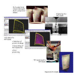
The coating by laser can be used to repair turbine blades. In the example of the image (Figure 8), in the first place, established a cyclical process chain. To repair a blade through coating by laser, the CAD data of the piece are used to generate the NC trajectories (tracks that they will be). If the CAD data are not available or if the dimensions of the blade changed with the use, it will be necessary to digitize the eroded blade geometry. To calculate the volume to generate, a blade of reference should also be digitized. Using a CAD/CAM system and CAD/CAM macros, this volume is divided into layers, and then created the NC ISO trajectories with the parameters of the process (the laser power, speed of scanning, overlap and filling or accumulation strategy). NC ISO trajectories become readable NC paths for a machine in a subsequent process step. The generated NC program is transferred to the NC control system. This yields a coating process by fully automated laser.
Modelling allows to predict outcomes and is an essential stage to understand the process and reduce the experimental work. The most reliable simulations are based on finite element method. In the ILT, created a model that took into account the flow of heat and mass within the weld bath as well as data from the injection of powder mass. With this, you can simulate the generation of a soul like that shown in Figure 9. At the moment, the model is being refined and will be used to optimize the strategies of coating for repairs.
Sheet steel is usually protected against corrosion by a galvanizing continuous followed by a coating coil polymer ("Duplex" technique). However, when later this sheet is cut into a manufacturing process, the metal surface of the edges is exposed to corrosion and therefore needs another coating. Some experiments have shown that it is possible to take zinc and polymer by laser. Since that break down Polymers at low temperatures, a direct injection (Figure 1) cannot be used. In these cases, is placed the beam laser ahead of the flow of dust, by heating the surface of the edge of the sheet. Polymeric particles melt by the transmission of heat. In Figure 10 you can see a sample subjected to a test of 1000 hours of salt spray: the part of the edge of the sheet that had been coated by RILSAN (layer of a thickness of 0.2 mm) does not show any corrosion. Similar results were obtained in the case of coatings of zinc (layer of a thickness of about 10-60 _m).

Cleaning and polishing with laser
For manufacture and final assembly of electronic devices are needed many cleaning and activation processes. Thus, it is necessary to eliminate surface weldable lacquers, pollution, waste of polymers, oxide coatings. In some processes (soldier, Union by adhesion) joints and coating (e.g. galvanized), cleaning of surfaces is especially important. Conventional cleaning techniques rely on chemical or mechanical processes and, in many cases, processing and disposal of waste are often expensive. On the other hand, the trend of the miniaturization requires the use of high precision cleaning processes. Technique laser eliminates all these problems associated with traditional cleaning techniques. Depending on the properties of absorbing coatings and source materials, CO2, ND: YAG or excímeros pulsed lasers can be used with pulses of 10 to 250 ns in duration. Due to the high intensity and short temporary interaction, non-metallic coating layers evaporate, while the metal surface of the substrate remains intact. An example of cleaning of electronic devices is the desescamado and decalcification of small blocks (Figure 11).
Another field of application of the laser is the grinding of surfaces (Figure 12). In this process, surface roughness, caused for example after a process of milling or deburring, alisan through the fusion of a thin layer of material. Very high accuracy of this process prevents the occurrence of rounded edges or geometric deviations. The speed tends to be between 0.2 and 5 cm2/min depending on the material, the initial roughness and required end. In order to perform these functions, in the production lines it is easy to integrate a nd: YAG fiber, continuous or pulsed laser. Some fields in which this technique could be applied are grinding of injection and casting moulds or medical instruments.
Selective cast with laser
In recent years (references 7-11) have arisen numerous processes of generative manufacturing (called rapid prototyping processes). In general, specific material or a composition is used in these processes. In order to overcome this restriction on a particular material, Fraunhofer ILT and TRUMPF are working on the development of a process laser selective function or SLM (short for Selective Laser Melting). The starting point, as in the generative processes of manufacture, is a 3D CAD model, which is subdivided into layers of a given thickness. The final piece is created using a repetitive process of laser sintering, in which information about the area and the shape of each layer are transferred by means of a laser beam. We highlight two fundamental differences in comparison to other generative processes: on the one hand, the material used is a powder of metal from a single component, as steel 1.4404 stainless, tool steel 1.2343 or titanium TiA16V4; on the other hand, the physical process consists of a complete recasting of the layers of dust with a metallurgical bond between layers and a density of approximately 100% in one step. Thanks to these characteristics, the scope of this technology has been expanded and extended the prototyping rapid to rapid manufacture of functional parts and tools in series. A close to 100% density can be obtained with the above mentioned materials. In addition, thanks to this high density, the SLM pieces presented good mechanical properties. The surface roughness and dimensional accuracy are decisive factors for the use and acceptance of the SLM process in the industry. In this sense, the roughness Rz of the SLM samples is around 30 to 40 degrees m and depends mainly on the structure of layers and molten particles to the surface of the pieces.


Fig. 15: Implant doctor after surface finish
Functional prototypes
The two most important objectives to be achieved with a working prototype are: the acquisition of a piece with some properties similar to the one produced in series and the reduction in the time of product development. Both requirements may be met with the help of a SLM process. Although the time of processing real of a piece may be greater due to the time required for the production of the layer, the whole process of manufacturing requires considerably less time than a conventional process. In traditional technologies, the production of moulds is a phase that time-consuming, especially. Through the use of materials in powder, it is possible to create virtually any type of geometry from CAD data; in this way, are no longer needed the semi-finished materials or phases of post-processing (for example, the creation of machining complex programs or other phases of manufacturing). In short: the selective foundry with laser allows to manufacture complex parts in less time and materials with properties in series.
An application of the laser in the prototyping is the manufacture of parts that are usually created in series by moulding by injection of metal (MIM). The SLM process allowed to shorten the time of manufacture of the pieces of the figure 13 two weeks (including the production of the mould) seven hours. The material is stainless steel 1.4404, which is also used for the production of parts in series.
Individual pieces
Another interesting scope of SLM technology is the production of medical implants. In recent years, the use of rapid prototyping technologies has expanded and become something common in this area. Using a special software CAD 3D models from the CT (computerized tomography) of patient data are created, and then taking them as a basis, creating master models through as the Stereolithography prototyping technologies. With the implementation of the SLM technology, is going to emerge a new chain of process for implants doctors, a string that is going to move directly from CT data to manufacture of the implant individual without intermediate phases such as the moulding. In this chain of production, through a fully automated production system, as a machine SLM, we could make individual pieces or pieces in small batches from different materials. The implant can be seen in Figure 14 and 15 has been made in seven hours, including all subsequent processes, such as the Elimination of the supporting structure and the surface finish. The implant is made in TiA16V4, an alloy of titanium with excellent characteristics of biocompatibility.
Almost unlimited freedom geometric has opened up new options in the design of the cooling channels, something crucial for maximising the manufacturing processes. The cooling of the mold Designer no longer has to worry about facilitating the subsequent processes with conventional technologies (e.g. drilling). Cooling channels can be designed, for example, so that they are the same distance from the cavity, adapted to the shape of the cavity (free geometry) and, in general, in areas inaccessible to conventional systems (Figure 16). Free geometry cooling, to improve the cooling, has a direct effect on the injection cycle time and the quality of the parts. The injection cycle interval decreases with the number of pieces produced, so the design of special cooling channels is a perfect technique for the inserts of mould in series. Against what is happening with other metals prototyping technologies, the SLM process allow to manufacture these inserts from materials in series, i.e., is a rapid manufacturing process. The possibility of using free geometry cooling channels and time savings make the SLM process an interesting supplement to the manufacturing methods of traditional molds, such as the EDM (machining by electrical discharge).
Conclusions
The exposed examples demonstrate the potential of the laser in surface treatments. An essential factor is the improvement of the quality of the beam (e.g., ND: YAG laser bar) and the development of new lasers for high efficiency (pumped by diode ND: YAG laser), advances that will help to reduce costs and help that the laser can be used in more applications. For the future, research will also address automation and process control, to increase the reliability. On the other hand, advances in modelling will be used to better understand the process and reduce the time of study of the parameters.
The use of materials of series in the SLM process offers new possibilities in the creation of prototypes and direct manufacturing parts. In addition, the possibility to produce pieces with geometric features complements conventional manufacturing methods in various fields (manufacture of implants medical, aerospace applications and manufacture of tools and moulds). Fraunhofer ILT will continue its investigations in cooperation with several industrial partners with the aim of achieving more complex geometries and expand the range of materials and composite materials. With regard to the manufacture of tools and moulds, the objective is to reduce manufacturing times, improve quality through free geometry cooling and increase the service life of parts.

Referencias
The German Ministry of education and Science (BMBF) has financed the project "Modulare Diodenlaser Strahlwekzeuge" (MDS) and for its part, the EC has financed project "Awfors", through which there have been some of the results on coating laser have been described before.