This news article was originally written in Spanish. It has been automatically translated for your convenience. Reasonable efforts have been made to provide an accurate translation, however, no automated translation is perfect nor is it intended to replace a human translator. The original article in Spanish can be viewed at Aspectos analíticos y tecnológicos del proceso de punzonado de chapa (2ª parte)
Equipment and technologies for sheetmetal
Analytical and technological aspects of the process of punching of sheet metal (part 2)
Mateos, S.; Rico, J.C.; Costs, E.; Valiño, G.
Department of manufacturing engineering. University of Oviedo
3. TECHNOLOGICAL ASPECTS OF THE PUNCHING
As in other sectors, the sheet metal forming machines, and in particular the punching machines, have evolved into machines increasingly automated and integrated with your working environment. These machines are usually numeric control machines, characterized by flexibility, allowing them to cover the manufacture of a wide range of parts on the same machine and with little influence on the costs of preparation of the same.
On the other hand, the gradual decline of the life of the products on the market, and the decrease in the number of pieces per lot, makes the punching machine of numerical control is present every day in the transformation of sheet metal. His versatility, progressive increase of the punching and the careers of working speeds makes, even in many cases, a more economical option to conventional presses.
3.1 Operations
Punching machines of numerical control machines allow to obtain pieces of sheet metal by means of three basic operations:
- Punzonado
- Chewed
- Conformed
The punching operation has commented widely previously and allows the realization of the coup of punching in a point (x, and) of the sheet. In the punching machine, in general, the position of the point of punching is the same, meaning that punch and matrix are in a fixed position of the machine, being the sheet which should move, together with the subject of the same system, to the point of punching.
The operation of mascado consists of the carrying out of consecutive fest and tab you in order to remove material in a wide area (emptying) or generate the outline of a piece. In this case, it must be borne in mind that the burden on the punch is not evenly distributed and not all the edges cut equally (Figure 14). The punching of sheet metal in large thicknesses should take into account the distribution of loads on the punch, so sometimes the sequence 1-3-5-2-4-1-2 - 3-4-5 in Figure 15 is preferred when it punzona with rectangular toolsoblong, etc.

Fig. 14 Edges of cut of the punch after the order of punching

Fig. 15 Punching sequence in bridge

Fig. 16 Material not removed in the chewing with circular punch
Contours can be obtained with a circular punch of varied form, but it introduces the problem that between two consecutive blows, there is a portion of material without deleting. Therefore, the generated form not matches the theoretical (Figure 16).
Is evident that with the increase in the passage of mascado, increases the height of the lug of the cutting edge. The decrease in the height of the highlight of the edge, decreases the step of mascado, being able to get to an inappropriate increase in machining time. In order to not leave the sheet material remains, the chewing in a straight line is done with hallmarks that have sections of straight sides (square, rectangular, oblong). In the case of curves, for the Elimination of waste, are used hallmarks of type banana, lenticular, etc. in combination with the turning of the punch and matrix (Figure 17).
In the notched or mascado of angled corners (Figure 18), requires the use of hallmarks of various sizes and only using a punch with a special form adapted to the sizing, you can totally eliminate material. It must start with the lower punch, to then continue with the punches in order of increasing diameter. The incorporation of the rotation of the awl makes that triangular shape tools also can remove all the material in the entalles.
Emptying presents another problem, and it is that you can leave pips or remains of material cut on the table of the punching machine. For example, in the case of the emptying of a circular shape (Figure 19), emptied initially with square hallmarks, would be pips on the table. To avoid this problem, one solution would be punching in first place with a punch of section equal to the square inscribed in the circle to generate, and then with a punch of circular section that has a sufficient diameter.

Fig. 17 Mascado with type banana punch

Fig. 18. Generation of entalles by chewing and punch in a special way

Fig. 19. Emptying of a circle through the use of several punches

Fig. 20. Realization of a rectangle by mascado
When a piece is cut, it can be cut completely in its outside contour, which is separated from the sheet, either be linked to it through micropuentes. The micropuentes are no overlap at several points in the outline of the piece the anorexiant leaving separations between 0.1 and 0.15 mm. The pieces are separated evacuated after the sheet of the punching press machine and therefore does not need a temporary stop of the machine to extract the piece. Tools to perform the micropuentes only can be square or rectangular tools. The number and location of the micropuentes depend on the shape and size of the piece and the thickness of the steel.
The order in which the operations of punching is another aspect to consider, because it directly influences the deformations that suffers the workpiece during the process. As a general rule, the punching through the holes of a smaller size, continuing progressively larger holes should begin. You must also start with the side opposite to the clutches of subjection of the sheet and continue in direction of the claws. For example, in Figure 20 the right way to proceed will be perform anorexiant 1 and 2, both from the opposite side of the grip towards them. Then, will be the mascados 3 and 4, in a sense, the other in the contrary.
The third type of operation, forming, allows operations by plastic deformation of the sheet. In general it's drawing operations, extrusion and coined that they can perform, for example, grids for ventilation in ways very varied, coined logos, etc. (Figure 21). It is common in this type of operation, the lower element happens to be functions of punch and the upper element acts as a matrix.

Fig. 21 Examples of made in punching machine CN of Mate Punch & die Co.
It is also important to take into account the height of the sheet distorted once, so that it does not interfere with parts of the machine or they can be damaged in subsequent operations.
3.2. Classification of the machines, punching machines
To carry out a classification of the machines, punching machines of CN in the marking, they will consider different criteria. In first place will be classified into two groups, depending on the frame or structure: type porch and type C or Swan neck. Given the importance of the game between matrix and punch, keep the coaxiality with a frame that is as rigid as possible, allowing preserving the perpendicular between the Bureau and the axis of percussion. A frame type portico is effective in this regard, but restricts the size of the formats and the comfort of their introduction in the machine (Figure 22). Another solution is the frame in the form of C or Swan neck with a forged core content in a welded frame (Figure 23).
In response to the drive of the punch system can be considered two groups of machines, punching machines: mechanical drive and hydraulic drive (Figure 23). The latter, must have a brake/clutch for the control of the pickguard (Figure 24).
By number of helpful, distinguishes between punching machines monoútil and multiútil. The monoútil punching machines have a single support to mount a matrix and a punch, so an only joint punch/matrix is ready to be used (Figure 25). In this type of punching machines, tool changing requires the replacement of the matrix and punch in the spindle, either automatically or manually, after selection of a new set of the store (linear or circular) (Figure 26). Meanwhile, the multiútil punching machines have several publishers to contain matrices and punches (Figure 23), so that the change of the T1 by T2 tool requires a movement to ensure that the punch and matrix of the new T2 tool and the drive of the same are aligned.

Fig. 22 Loved punching machine of gantry type

Fig. 23 Punching machine Trumpf type Swan neck

Fig. 24. Hydraulic drive

Fig. 25. Mechanical actuation of Goiti
Another feature of the machines is the possibility of having rotation synchronized (via CN) of the portapunzón and portamatriz on its own axis, so that the punch can form any angle with the axis X (Figure 27). This feature is often called Auto-Index and in the case of a monoútil punching machine, all tools shall dispose of it, while in the punching machines of turret, only a limited number of the portapunzones and portamatrices her.
According to the number of controlled axes (Figure 28), we can speak of: CN punching machines of 3 axes (axis X, axis and and Z axis of depth of the punch control), punching machines of 4-axis (axis X, axis and Z axis of depth of the punch control and T axis of tool change), punching machines of 5-axis (axis X, axis and Z axis of depth control of the awl, axis of rotation of the punch and axis of rotation of the matrix B), CN punching machines of 6-axis (axis X, axis and Z axis of control of depth of the awl)(, T axis of tool change, axis of rotation of the punch and axis of rotation of the matrix B).
According to the Bureau of support, we can speak of: punching machines with table of phone support or fixed support table. In order to not make marks on the surface of the sheet, in its motion on the table of punching, latter may have balls and/or brushes. An important feature of the table of punching is the existence of hatches or ramps for the evacuation of the cut piece and that should never be on the table. Some machines have the option of a programmable table which allows the displacement of part of the support desk, and thereby increase the size of the area for the disposal of the cut pieces.

Fig. 26. Monoútil punching machine with linear Trumpfl store
")
Fig. 27. Drawing of the punch and matrix on its axis (Auto-Index)

Fig. 28 Lines of a punching machine Omes

Fig. 29. Claws of subjection of the sheet

Fig. 30 Prancing to the dislodged from the sheet
The subject of the sheet on the machine is performed through grip located on the X axis, usually powered hydraulically (Figure 29). The position of the claws can be programmable and allow the dislodged the sheet through the subject of the same by the prancing and the displacement of the point of subject (Figure 30). This provision allows theoretically unlimited veneers manufacturing in X, and of course where the table is extended to support the eventual cantilever of the sheet. It is possible that the claws can retract to the passage of the punching head and thus avoid the loss of material in the area of the claws, reduces the preparation time due to the positioning of these and save programming time, that must not determine the position of the claws.
It is also possible to automate the process of loading and unloading of the punching machine, with a view to integrating it with other machines dedicated to forming of sheet metal (feeder coils of sheet metal shears, folding, etc.). Generally, in the punching machines, automatic feeding is done by manipulators using suction cups as devices for the subject of the plates.
Some manufacturers, incorporated on the same machine, punching press other technologies of court, such as laser or plasma cutting. Although this is a rare case, it can increase the possibilities of using the same machine.
3.3 Tools
The tools for the punching machines of CN are not standardized as it is the case of other cutting tools, so there are a variety of types and configurations. For this reason, certain manufacturers offer adapters to use tools from other manufacturers. The tools for the punching machines of CN can be classified according to the number of forms in punzonadas:
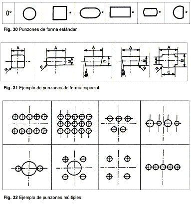
- simple Tools, that realise the cut of an only form with each hit of punzonado. To his time, can divide in which have a standard form (figure 31) or, special forms (figure 32).
- multiple Tools, that realise with a hit of punzonado the simultaneous cut of more than a form on the sheet (figure 33).
Another way to classify the tools is in response to the type of machine punching machine which will be mounted, either a monoútil or turret punching press. The latter, are classified according to the size of the accommodation of the station (Figure 34):
- Type To, groups for accommodations of 12,7 mm (0,5 inches), that allow punchers of 1,6 to 12,7 mm of diameter or forms in the interior of a circumference of diameter 12,7mm.
- Type B, groups for accommodations of 31,7 mm (1,25 inches), that allow punchers of until 31,7 mm of diameter or forms in the interior of a circumference of diameter 31,7mm. These tools can mount punchers DIN 9861 of the type D between 5 and 17 mm.
- Type C, groups for accommodations of 50,8 mm (2 inches), that allow punchers of until 50,8 mm of diameter or forms in the interior of a circumference of diameter 50,8 mm.
- Type D, groups for accommodations of 88,9 mm (3,5 inches), that allow punchers of until 88,9 mm of diameter or forms in the interior of a circumference of diameter 88,9 mm.
- Type And, groups for accommodations of 114,4 mm (4,5 inches), that allow punchers of until 114,4 mm of diameter or forms in the interior of a circumference of diameter 114,4 mm.
")
Fig. 34 Accommodations for the punches in the turret in a punching machine LVD (DELTA model)
Each manufacturer of machines, punching machines of CN has a particular form of Mount in the turret of the sets B and C. Matrix The joint punch should properly adjust in the accommodation, as it moves through the accommodation during the punching of sheet metal.
On the other hand, the tools for punching machines monoútil can be classified into two types, according to the element that presents the system of Union to the machine:
- System of union had in the punzón. In this type of tooling, the punzón and the plate separadora are not, generally, joined in a cartridge, realising his setting in the punzonadora, separately (figure 35).
- System of union is in another element and the punzón is lodged in a cartridge. The cartridge includes the system of extraction equipment equipment of the punzón, generally of type resorte, and the plate of separation (figure 36).

Fig. 35. Union of the punch directly to the machine.
Outline of the manual and automatic change of Trumpf machines.

Fig. 36. Outline of a cartridge for the erection of the punch of Matt Punch & Die co.
In order to reduce non-productive times arising from changes in tool, manufacturers have developed a set called Multitool, which allows the control of the rotation of a shaft, the alignment of the pickguard with different punches (Figure 37). Thus, switching from punch without having to make the turn of the turret tool holders or the change of tool. However, with this kind of useful point in which the punching is performed changes, so that the control should be the correction of the same, moving the sheet appropriately.
The material of the punch for less than 3 mm thickness, usually steel fast F-5603 (AISI M2) or F-5221 (AISI D2), which have good resistance to wear and a medium-low tenacity. For 3 to 8 mm sheet steel F-5220 (AISI 01) or F-5227 (AISI A2), which are more strenuous than the previous ones but less wear-resistant steels is recommended. As is the case with other cutting tools, the punches are also covered by ICT, TiN, CrC, W2C and ICT TiN. Thereby significantly increases the life of the punch, with a slight increase in the cost of the same. The punches may have ridges in the form of interchangeable elements, which are only replaced the parties subject to greater wear.
As mentioned above, the elastic recovery of the cut material is that it is retained in the matrix. In this sense, the action of the Court for a second piece, vow to press on the first cut, facilitating its removal. However, the effort required in the second cut will be higher than the first. To reduce this effort, the cutting contour of the matrix, is experiencing a gradual increase (Figure 36), so that on the descent of the cut pieces, lateral friction resistance is decreasing. In this way, only the upper part of the parent Panel does not work, and the awl fricciona only on the edge of the matrix. On the other hand, the taper of the matrices or small bumps, prevents the return of the material cut to the table of the machine.
Given that the game is given in the matrix, their selection is made according to the thickness of the steel to cut. For this reason, it is usual that workshops, take a punch and several arrays to combine in order to allow different sets of court and adapt to different thickness of the sheet. its use with different thicknesses of sheet metal and materials.

Fig. 37 A tool laser Inc. multitool drive and
tool multitool Mate Punch & Die co.
tool multitool Mate Punch & Die co.
Related Companies or Entities
Danobat, Division Sheet Metal
TRUMPF Maquinaria, S.A.