Effect of the interaction design-manufacture in the modification of the contact in conical gears-spirals
To. Martínez City L. N. López of Lacalle and J. To. Sánchez, Department of Mechanical Engineering UPV/EHU
J. Loves, Group Egile
To. Sources Aznar and I. González Pérez, Department of Mechanical Engineering, UPCT
11/12/20131. Summary
Has checked that splits of the problems of durability and reliability of the gears of conical type-spiral root in the focalización of the zone of contact between corresponding teeth. This zone of contact can change in function of the strategy of design, machine of manufacture and even the final setting of the pairs of wheels. Like this it shows in several practical cases explained in this work. Also it does reference to the systematic measure of this type of gears so much by simple technicians as in MMC.
2. Introduction
The process of manufacture of a gear goes to depend of the type that want to achieve [1]-[8]. In this introduction goes to do a review to the existent technologies in the manufacture of gears depending on his type as well as the evolution that have suffered these technologies along the years.
2.1. Cylindrical gears
The gears can manufacture according to different processes, between which can distinguish the methods of reproduction and the ones of generation. The first present a very high productivity, but require a high investment in machinery or tools. The seconds are less productive but more universal.
The methods of reproduction [1] obtain the final surface of the gear directly, between them distinguish :
- Smelting: in case of gears of big dimensions
- Sinterizado from metallic dusts.
- Forges [8] and back finishing.
- Broaching: For inner gears of small size.
- Start of shaving:
- Cut by strawberry module. It employs an useful of cutting that reproduces the exact form of the gaps that go to delete, These methods do not pose differences regarding the enclosed cycle proposed, and are out of the field of this work.
- Cut in machine of 5 axles[10]. Thanks to the precision and to the repetitividad of the new models of machines multitaleatherg and scheme of 5 axles is possible to manufacture gears in a universal machine and no in a machine talladora of gears as traditionally. It is not for production in mass. It contributes flexibility not being limited only to gears. The problem is that this process is not valid when it speaks of gears cut of high quality (ISO 1-3).
In the case of the methods by generation[1] the idea is that the tool of cut generate precisely the profile conjugado of his teeth, of the same form that would exist a contact between profiles if the wheel manufactured meshed with her. The 'point of contact' would be in the cut the 'point of profile generated'. The cinematic of the process imposes it the machine of cut, equivalent to the that would be the contact between profiles. They exist two types of process:
- Generation by strawberry mother (hobbing): The tool turns on his axis and has form of screw sinfín. Therefore his longitudinal section is similar to a zip.
- Mortajado With zip or pinion: the process of cutting produces because of the sharp edges of the tool, and to the existence of a continuous and fast movement of vaivén (designated industrialmente mortajado). They exist two modalities, generation with zip and generation with pinion.
2.1.1. Evolution of the machines talladoras along the history
In the past, the only way to establish a connection between the cutter and the gear to cut was mecánicamente. All the movement of generation of the gears came conditioned by the relation of transmission that entered in the 'box of changes' of the machine. This way to work condemned the possibility to realizar variations of an agile way. In summary, the gears were generated by a machine whose heart was a system of gears. At present all this process has been substituted by the electronics equipment dealers equipment dealers (CNC) in such a way that any movement is controlled by an engine. Of this way has the possibility to realizar any change and any regulation to be able to improve the process.
2.2 conical Gears
The concept that applies for the manufacture of conical gears is exactly the same that it uses for the realisation of straight gears. Achieve that the tool generate the movement of mesh.
2.2.1. Conical gear of straight teeth
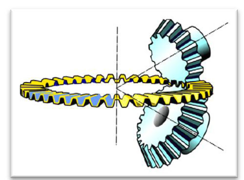
Exist different methodologies for the generation of this type of gears:
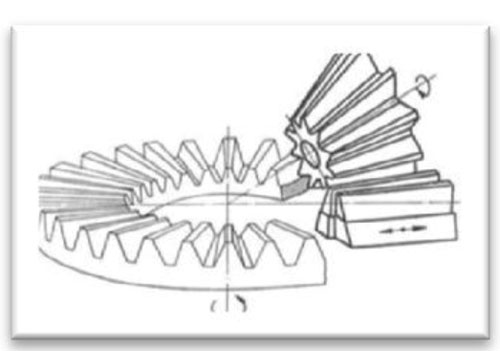
Appear 2: to) Cutter of blades.
2.2.2. Gears espiro-conical
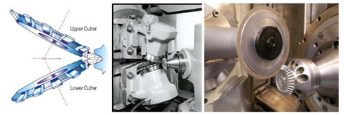
Although a priori the manufacture of this type of gear can seem much more complicated, the realisation of these gears has the same principle that the previous types mentioned, that the tool substitute in his movement that profile with which goes to go in in contact the gear.
Exist two totally differentiated currents to manufacture these gears.
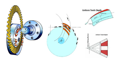
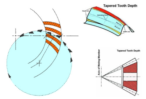
2.3. Evolution of the machines for gears espiro-conical
The changes suffered in the machines along the years has been produced by a continuous interest in being able to control increasingly each parameter of the process and not depending on a mechanical and enclosed movement. A modification in the surface of the piece supposed a 'rediseño' in all the cinematic chain that generates the profile of the tooth.
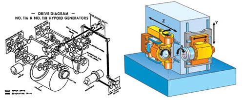
The new technologies entered in the last years have propiciado a greater possibility of regulation of all the parameters that affect to the gear. In a gear espiro-conical this is of big importance since a small modification can do that the contact between surfaces improve ostensiblemente. In the figure 6 shows the complexity of the necessary mechanism to generate a gear espiro-conical as well as the last technology for the generation of these gears.
3. Cases of study: gears espiro-conical
The way to work with this type of gears differs totally of what would be with a cylindrical gear of straight teeth. Like this, when it wants to work with gears of straight teeth, all the phases that take part from his design until his setting can be independent between them. The control of these gears is perfectly defined in the international norms by what measure and correct the failures is relatively simple. Besides all the corrections to realizar are by general norm, very intuitive. The setting of a couple of gears does not influence too much in the zone of contact since it parameters to modify are scarce. The intercambiabilidad between wheels is one of the points to attain in his production and setting.
In the gears espiro-conical the concepts used up to now dispel . The phases that engloban the cycle of the piece from the design until the setting of the same turn into an alone. In this case, it can not work of independent way between ones and others. All the phases go to be joined inside a global cycle.
In this article poses a method of work to reduce to the maximum the number of necessary iterations, by means of a method of work realimentado between the first stages of design-manufacture-control of quality. Besides, it enters the manufacture of the piece by means of the process of rectified from solid, that is a process very headed to short series. The rectified besides induces the problem added of burned and control of the process.
3.1. Typology of piece to study
The sector to the that go to go directed the pieces of this case of study, is the aeronautical sector component manufacturing sector component manufacturing sector. This sector has a series of requests that do not have the rest of sectors. The pairs of gears espiro-conical used in aeronautical sector component manufacturing sector component manufacturing have to have the best quality regarding error in passing refers arriving to be necessary to fulfil the quality DIN 1 to DIN 3. By his place the reliability of the components is a critical factor in any component entered inside an aeroplane. The pieces treated are pieces known like criticisms, these are those that in case to fail the aeroplane could not follow flying.
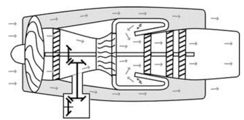
Equally important are other appearances like superficial finishing, background radio of the tooth, achieve an error of low transmission, high mechanical resistance and low weight. The main challenge to achieve, is to achieve a 'ease-off' in the phase of design that was acceptable and treat to reflect it in the reality. For this purpose and the requirements of quality mentioned previously, is necessary to have of the viable machines to achieve it.
To be able to surpass the requirements of wear and mechanical resistance, these pieces like normal general will have to go with a superficial treatment that them of hardness. In this case, the superficial treatment is a cementado. The material of game is an And16NCD13. The previous state to the treatment is recocido. It will ask him a layer of cementado between 0,65 and 0,8 mm. After the cementado will be necessary an operation of temper and revenido. The superficial hardness to achieve is of 58-62 HRC. Also it is necessary to mention that the number of pieces to manufacture are not elevated. No more than 20 pieces.
4. Methodology of work. Enclosed cycle
In the figure 8, shows the sequence of work to be followed to achieve realizar a set of gears with the characteristics of quality defined previously.
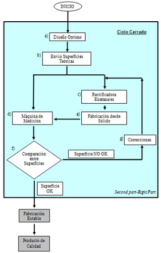
The first phase of the cycle, is the one of design (8to). In this phase is where is cream the conception of the surfaces of the gear, here will decide how will have to be the contact between surfaces for a correct operation. Once finished this phase, the surfaces will be envoys (8b) to the machine for his manufacture (8c) and to the machine of control (8d) for his back measurement. After receiving the surfaces in the rectificadora, will mechanise the surfaces (and). This first manufacture will generate some surfaces that will not be the ideal, by this, the pieces have to measure to indicate the differences between the theoretical surfaces and the real achieved in the rectificadora (8f). After analysing the existent differences, the department of engineering will realizar the necessary corrections to arrive to the ideal surface designed (8g). With these new corrections, goes back to the machine to go back to rectify the surfaces. After this enclosed cycle, the pieces that go out after these operations are pieces whose surfaces go in inside the limits of quality demanded. Working of this way, involving to all the phases (design-manufacture- control) achieves a stable production from the first piece. Once that it achieves the first piece, the process of manufacture can continue without depending on the other departments since the quality of the piece already is ensured thanks to the methodology of work explained.
In the following sections shows more in detail each phase of the process.
5. Stage 1. I design gear espiro-conical
Like first phase, treats to look for a set of gears espiro-conical that they are able to provide some characteristics of durability and high resistance. Therefore, has to look for at all times that the zone of contact was that that provide the lower error of transmission [12], in addition to that the tensions of contact do not surpass critical values for the material.
To realizar the study and the improvement has to split of the initial design to see if this is valid or if by the contrary can improve . [13] In this case, the analysis of the couple of gears provides the following results.
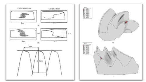
The result obtained in this first phase of design is not the wished. The zone of contact does not follow an ideal theoretical line, in fact neither approaches. Regarding the error of transmission, the values are too high so that during the operation do not exist any problem, therefore it neither is valid. Finally, it sees that they exist zones where the tension of contact is too high.
The first step in the optimisation is directed in the research of the best steering of contact that was able of the greater error of positioning. As it can see in the figure 10, the new steering of contact offers a better distribution of the area of contact improving ostensiblemente the operation of said pair of gears. Adding light modifications in the parameters of machine achieves a profile of the flank improved.
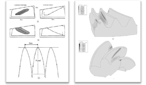
Because of the big complexity of the problem, and because of the type of piece to the that faces up . The best method to achieve attain the requirements of quality, is the method of rectified by independent flank. In this format of manufacture, each flank manufactures without taking into account the contrary. It achieves that any modification that realizar in a concave flank for example, was not copy to the convex flank, since the tool will not be never in contact with the two flanks at the same time.
6. Stage 2. Manufacture by rectified from solid
In this case, will use two grind identical but that with hindsight one will go directed to the convex flank and the another to the concave flank. Because of the qualities that want to achieve , has to ensure that the pieces in the moment in which they arrive to the machine, have some very specific characteristics of quality. Usually, it needs a face of support and a diameter of reference to be able to centre the piece in the machine. It is evident that if before beginning to cut the gear, this already brings intrinsically a previous error, this error will be addition to the gear. It is therefore that this is a key point.
Another part, the same of important, is the design of the tooling. it is thinking In achieving pieces in quality DIN 1-2 therefore, the form in which it goes to go the piece tieed up and supported in the machine comports a big importance. This article is not object of study of all the different typology of toolings that are necessary, therefore it does not go to go in in detail in this subject. In definite, the total error that obtain in the gear will be the sum of all the inherent errors caused by divergences in the process of manufacture.
Finally remains to define in which machine go to realizar the operations of manufacture (Stage 2) and of control (Stage 3).
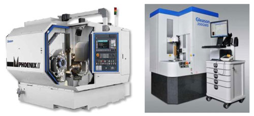
The machine of which has to realizar these essays is the machine Phoenix 275G with cabezal of high speed of the company Gleason, a machine of rectified compact and versatile that will help to achieve said purpose as long as it take into account the restrictions that imposes this machine:
- Diameter of grind. 69 mm ≤ Ø ≤ 230 mm
- maximum Width of the tooth = 58 mm
- maximum Revolutions of the spindle = 12.000 rpm.
- Primitive diameter maximum of the crown = 275 mm
This machine also offers the possibility to do the rectified from solid. With this process, avoids have to buy new tools to realizar a previous desbaste of the piece, wins time (tuned of new tools) and money (does not be necessary to invest in different tools).
7. Stage 3. Measure and readjustment of parameters
When one goes to put to manufacture, does not have of the same data of control that in any another typology of gears (individual Error in passing (fp), total error of division (Fp), total error of propeller (Fβ), total error of profile (Fα), etc.) it is thus, that the only that can do is to treat to manufacture the surface more resembled the designed previously. To be able to see the existent differences between what manufacture and what has designed puts to disposal of the essays the machine of measurement of gears 350 GMS of the company Gleason.
Once defined the toolings, tools and machines is the moment to begin to manufacture. In this instant needs that the phase of design, manufacture and control are joined. To continuation proceeds to enter a methodology of work by means of an enclosed cycle between them to be able to realizar a stable manufacture.
After having realizar the convenient design looking for the optimum contact between the surfaces, will have to command these surfaces generated to the machine by means of a post-processed. At the same time, for a back control in the machine of measurement, also will send said theoretical surfaces to the machine of control. As it has commented previously, the method of manufacture that goes to use is the one of independent flanks. The process of necessary manufacture to be able to realizar properly the pieces has determined that it was:
- Desbaste Of the convex side.
- Desbaste Of the concave side.
- Cementado.
- Finished convex side.
- Finished concave side.
- Attack nital.
Is evident that realizar the process in so many phases can arrive to seem excessive but because of the big complexity of the problem, is the most reliable way to ensure the quality of the product.
Is time to to begin with the first step the desbaste previous to the cementado. Once mounted grind it and the piece in the machine can begin to realizar the cycle of work in the machine defined in the phase of previous design. Once finished the operation, will check which type of surface has generated . To be able to see that it has obtained , will proceed to the measurement by means of points of the surface. In this case, the mesh chosen is a mesh of 9 columns and 5 rows. That is to say, the surface will remain determined by 45 points.
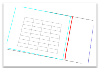
As it has commented does not have of parameters of control to know if it is well or badly, only exists a theoretical surface that will have to contrast with the surface generated. In the figure 13 shows the comparison between the theoretical surface and the surface mechanised.
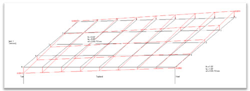
The black mesh represents the theoretical surface previously designed. The red sample cual is the current distortion regarding the theorist. To be able to correct these deviations, goes back to go in at stake the phase of design. After receiving the information of the errors, can do the necessary modifications to correct said error. It can suceder that the error was so high that there is not way to correct it. In this point always is necessary to treat to do the simplest corrections that are possible since what more complicated are, greater will be the complexity of the movement to realizar by the machine. If the error is too high, can that although they realizar the pertinent corrections, can not arrive to the theoretical mesh.
Once that they have the necessary parameters to correct the errors, have to go back to command the machine, so that in the next cycle realizar the corrections. As it can observe , after mechanising and go back to measure obtain the following results:
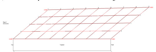
Once achieved one of the flanks, is the moment to continue with the following. The process to be followed it would be exactly the same that for the previous. Command the surface of the flank to the machine 275G and to the machine of measurement 350GMS. Realizar the cycle of mechanised and later measure. After the measurement, take out the differences between the theoretical and real mesh to be able to again in the phase of design, correct said errors. Again they need to be related the phase of design, with the one of measurement and the one of manufacture since to do the pertinent changes, the machine will need to receive the changes to realizar.
As it can appreciate , the typical concept of the workshops, trying be independent of engineering does not work in this type of pieces. Both groups have to work together if they want to achieve a product with some so special requirements.
To complicate even more the manufacture of this gear, comment previously that would owe to carry a cementado [15]. This cementado realizar after the desbaste explained previously. Here it can have diversity of opinions, why lose the time in taking out a so good surface if it is a desbaste? The answer is clear, after the operation of cementado, the gear suffers a severe deformation by what could not finish the gear and later treat it since it would be impossible to fulfil with the requirements of quality. Another reason by which adjusts so much the surface in the desbaste, is because of this way already has the best configuration of machine to achieve the surface of the theoretical flank. And to finalise, is necessary to have a layer of cementado perfectly distributed along all the gear and from here that it need that the surface desbastada was the more resembled the final surface finished.
After realizar the cementado, all the faces and diameters that had used previously to support and centre the piece in the tooling remain useless. The piece needs to go back to be mechanised to achieve some registers where can support again the piece.
Once that it has a clean zone can go back to mount the piece in the tooling to begin with the operation of finishing. The operation of desbaste realizar with the method of rectified from solid, therefore in each past existed the same quantity of material. Now, after the cementado and with the deformation suffered does not have the same material in all the flank what goes to complicate even more the tuned to finalise the gear. The current situation is that it has a tooth cementado with different material along the tooth. If to the hour to rectify, exceeds with the power applied, can suceder that it exceed the temperature of revenido, have a structural change in the piece and therefore the piece suffer burned. If this sucede, the piece remains directly refused.
The process to be followed to finish the piece, is the same that it has used for the desbaste. Has to go back to use the interaction between manufacture-design-control to have the surface wished.
To be able to validate the process, as it has rectified on zone cementada, has to realizar an attack nital to the piece to see that in any moment this piece has suffered burns in his surface. The process of nital to realizar is the following:
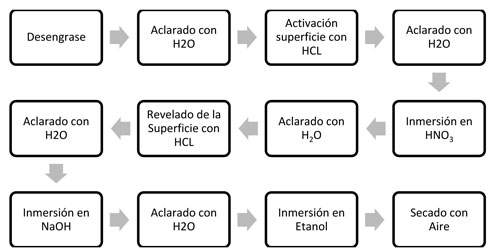
Appears 15: Process for attack nital.
8. Final setting
That the piece have surpassed the previous requirements of quality, does not suppose that the piece was perfectly smart for the manufacture in series. To see if really the manufactured is what designed , it is necessary to realizar a last manual operation. In this operation will do work the gears in his position of setting to see where remains the zone of contact.
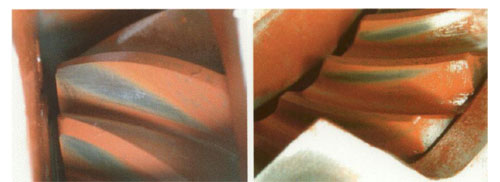
If this contact remains in the zone wished will be able to give by valid the design, the manufacture and the setting. If it is not like this, they exist several possibilities to be able to modify slightly the contact along the flank that show to continuation:
- Go up and go down the contact if it enters or takes out the pinion inside the crown.

- Displace the contact along the flank, to a side or to the another, going up and going down the pinion in the steering V.

These modifications in the setting have the disadvantage that from this moment, to keep the properties in the zone of contact that have achieved this pair of gears, will not be able to exchange with other gears. These two, would be joined for life.
9. Conclusions
In this work has presented a method of work that minimises the time of production of complex gears, and besides have presented lines of development that allow to go in in projects of design and optimisation of complex transmissions and of high responsibility. Of this form is possible to manufacture gears that ensure at least 'second part- rigth part', in the complex problem of the conical spirals. Where from the start until his manufacture, all and each one of the parts has an importance determinant in the product.
The work besides has allowed to generate and update new know how that is already integrated in the formative plans of the degree of Ing Mechanical and a Master, and a group consolidated in our surroundings that can integrate in complex projects.
Of this form breaks a reality that to date has occurred, that manufacture gears but with the weakness that all the phases of the gear were not interrelated between them.
Solves the problem of the rejections of pieces like consequence of the realisation of the gears by means of proof and error.
10. Gratitudes
The author wants to appreciate the financials received of Mimeco inside the Project Innpacto Enngrana that has made possible the achievement of this work.
References
[1] K.-D. Bouzakis, And. Lili, N. Michailidis, Or. Friderikos. Manufacturing of cylindrical gears by generating cutting processes: To critical synthesis of analysis methods. CIRP Annals - Manufacturing Technology, Volume 57, Issue 2, 2008, Pages 676-696
[2] R.Endoy, Gear Hobbing, Shaping, and Shaving: To Guide to Cycle Time Estimating and Process Planning, SME, 1990
[3] Prem H. Daryani, The Art of Gear Fabrication, Industrial Presses Inc., 2001
[4] Franklin Day Jones, Henry H. Ryffel. Machinery's Hadbook. Industrial Presses Inc., 1961
[5] Joseph R. Davis, Gear Materials, Properties, and Manufacture, ASM International, 2005
[6] Angulo, C.; López of Lacalle, L.N.; Agirrebeitia, J.; I paint, Ch.; ELEMENTS OF MACHINES. ISBN: 978-84-95809-27-8. Section of Publications of the And. T. S. Engineering of Bilbao, 2007
[7] B. Karpuschewski, H.-J. Knoche, M. Hipke. Gear finishing by abrasive processes. CIRP Annals - Manufacturing Technology, Volume 57, Issue 2, 2008, Pages 621-640
[8] G.G. Baránov. Course of the Theory of Mechanisms and Machines. PUBLISHER MIR, 1980. Pages 209-326.
[9] And. Doege, H. Nägele. FAITH Simulation of the Precision Forging Process of Bevel Gears. CIRP Annals - Manufacturing Technology, Volume 43, Issue 1, 1994, Pages 241-244
[10] S.H. Suh, W.S. Jih, H.D. Hong, D.H. Chung. Sculptured surface machining of spiral bevel gears with CNC milling. International Journal of Machine Tools and Manufacture, Volume 41, Issue 6, May 2001, Pages 833-850
[11] Vilmos V. Simon. Influence of tooth modifications on tooth contact in face-hobbed spiral bevel gears. Mechanism and Machine Theory, Volume 46, Issue 12, December 2011, Pages 1980-1998
[12] Chung-Yunn Lin, Chung-Biau Tsay, Zhang-Hua Fong, Computer-aided manufacturing of spiral bevel and hypoid gears by applying optimization techniques, Journal of Materials Processing Technology, Volume 114, Issue 1, 4 July 2001, Pages 22-35
[13] Faydor L. Litvin, Alfonso Sources, Kenichi Hayasaka. Design, manufacture, stress analysis, and experimental tests of low-noise high endurance spiral bevel gears. Mechanism and Machine Theory, Volume 41, Issue 1, January 2006, Pages 83-118.
[14] Guenther. Interpretation of bevel gear topography measurements. CIRP Annals - Manufacturing Technology, Volume 60, Issue 1, 2011, Pages 551-554.
[15] K.-D Bouzakis, N Michailidis, J Anastopoulos, S Kompogiannis, G Erkens, P.J Roudnik. Geometry and coating parameters effect on cemented carbide sticks cutting performance used in bevel gear manufacturing, Surface and Coatings Technology, Volume 153, Issues 2–3, 15 April 2002, Pages 148-154
[16] Ying-Chien Tsai, Wei-Yi Hsu. The study on the design of spiral bevel gear sets with Circulate-arc contact paths and tooth profiles. Mechanism and Machine Theory, Volume 43, Issue 9, September 2008, Pages 1158-1174
[17] Cao Xuemei, Fang Zongde, Xu Hao, His Jinzhan. Design of Pinion Machine Tool-settings for Spiral Bevel Gears by Controlling Contact Path and Transmission Errors Original Research Article. Chinese Journal of Aeronautics, Volume 21, Issue 2, April 2008, Pages 179-186
[18] Vilmos Simon. Head-Cutter for optimal tooth modifications in spiral bevel gears. Mechanism and Machine Theory, Volume 44, Issue 7, July 2009, Pages 1420-1435
[19] Alessio Artoni, Marco Gabiccini, Mohsen Kolivand. Ease-off based compensation of tooth surface deviations for spiral bevel and hypoid gears: Only the pinion needs corrections. Mechanism and Machine Theory, Volume 61, March 2013, Pages 84-101


