Integration of multitasking for the production of blades
A. Calleja, A. Fernández, A. Rodríguez, A. Lamikiz, L.N. López de Lacalle of the Dept. of mechanical engineering (UPV/EHU), ETSI in Bilbao
25/07/2013The manufacture of rotary presses components of high value added is critical given the complexity of his geometry. The presence of these components extends to several sectors like the aeronautical sector component manufacturing sector component manufacturing, the car or the one of the power. Some clear examples of this type of rotary presses geometries are the shovels of propeller, álabes for turbo-machineries, levy forged or axles of levy of smelting that have to be mechanised, etc. Nowadays exists a firm tendency to the realisation of all the operations that conform a piece in the same machine, the designated like mechanised multitaleatherg or multitarea. The greater advantage is that it does not lose in any moment the system of reference of the piece along all the operations and minimises the possibility of errors at the same time that it reduces the final time total. The concept of machine-tool is evolving to the new concept of multitarea, and even processes no traditional like the temper by laser, laser cladding or burnished carry out in the same machine without altering the initial setting.
This article defines a hybrid process for the manufacture of a blade of a propeller in a multitasking machine. The machining of the blade is carried out by the successive application of three techniques. First be a lathe-milling operation (turn-milling) to define the preform. In second place was torno-fresa the surface to top of ball (turn-ball end milling) for the contoured surface and finally polishes (burnishing) to improve roughness and increase resistance to fatigue of the piece. These processes are model to determine its optimal parameters.
This process allows complex functional components with high-integrity, quality and short process times. The comprehensive view of the processes can be assumed to produce high value-added parts that also have interesting functional properties, in relation to accuracy, resistance to fatigue, etc. In short, shown as possibilities for a multi-tasking machine open new high value-added processes.
1. Introduction
The manufacture of blades is becoming more common in sectors such as aeronautics and energy. Compose your geometry a series of complex surfaces subjected to harsh working conditions. For its good manufacturing practices, it is necessary to take into account the aerodynamics of the piece and the efforts to which is subject, it is necessary to comply with all the requirements for the final part.
1.1 Streamlined and forces acting on the blade
This type of blades are formed by two warped surfaces attached at its end to bushing. As it can be seen in Figure 1, the forces what Act on this type of blades are:
- Thrust of the force of the wind on the blade parallel to the direction of feed by introducing an effort to Flex the surface of the blade.
- Centrifugal force due to the rotation of the blade itself and tends to push the blade of its central point.
- Torque that is place on the blade as a result of the possible forces that can exercise the wind and tends to twist blades them against a lower thrust angle.

Figure 1.Efforts on the section of a blade
2 The process of manufacturing the blades
The manufacturing process of blades studied in the article relies to the so-called concept of multitasking which gathers all required manufacturing processes by the praise on the same machine. As a result of grouping them in a single machine and therefore, a single attached piece, will reduce the possibility of errors due to constant shipments of parts from one machine to another. Manufacturing times are reduced in this way also. Also tied it allows maintaining the same reference system and avoid possible problems due to the constant changes of reference.
Initially, the piece needs to undergo a process of lathe and milling to make roughing it up to get a piece as close to the final piece. Subsequently, the finish is of the praise by lathe milling with ball end cutter. In some cases, applying a balanced machining or milling pinch allows faster manufacturing processes through the implementation of two operations at the same time. Finally, is burnishing the piece to improve the final roughness and fatigue of the same life.
2.1 Lathe-milling
The lathe-milling is a relatively new concept within manufacturing technologies in 4- or 5-axis multitasking machines. For this operation it is necessary to provide a simultaneous rotation both the workpiece and the tool. This process, depending on the spatial position of the axes of rotation, can be classified as lathe-milling coaxial u orthogonal [1]. It is called coaxial when the axis of rotation of the tool and the workpiece are parallel to each other. The process is called orthogonal when the axis of rotation of the tool is perpendicular to the piece.
2.1.1 Lathe-milling coaxial
In this type of lathe and milling (Figure 2), tool attacks to the piece with the flank of the tool at all times. A correct choice of the strawberry to be used is critical for the technique provide satisfactory results, so strawberries squaring, due to its design, which is best suited to this process.
This option is suitable both for machining both exterior and Interior when it's a piece of revolution or not. For the implementation of this technique the workpiece rotation is relatively slow compared to the speed of rotation of the tool. This involves a series of advantages as due to the kinematics of the process produced short chips, even when it comes to machining of ductile materials. In the case of machining very slender cylindrical parts, the low rotation speed prevents excite the workpiece at high frequencies in conventional turning.
To use this technique of lathe and milling required that the machine tool is able to interpolate 3 or 4 axles in continuous. The kinematics of this technique is presented in the following figure. Since the rotation of the tool should be always used in the same sense, as a result of the spatial arrangement of the cutting edges, should pay attention to the direction of rotation of the workpiece. It will be the direction of rotation which determine if the machining is opposition or in accordance. Both operations reflected in the figure are consistent, because it is the strategy that provides better results in terms of dimensional tolerance and surface finish.
Some particular features of this technique are:
- Internal machining without the need of having a preliminary hole can be through the use of a proper Strawberry
- Not cylindrical surfaces can be generated as shown in the example of previous figure
- Narrow channels can be machined
- The technique ideal for Interior and exterior threads with thread milling machining
- The main disadvantage of the technique is that a high cantilever tool is necessary for deep cavities.

Figure 2.Scheme operation of lathe and milling cinematic coaxial and example of application.
2.1.2 Lathe-milling orthogonal
The process (Figure 3) is called orthogonal when the axis of rotation of the tool is perpendicular to the piece, being applicable only for external machining. This technique provides a number of advantages:
- Good results are obtained when machining of thin-walled parts, since efforts cut are smaller than in conventional turning.
- Possibility of using cantilever minor tools, which gives the process a greater stability when the boot of material rate is large.
- If it is endowed to a high speed rotary tool and appropriate geometric parameters are used, it is possible to obtain a surface quality very good, comparable even with grinding [2].
- The evacuation of the chip is simpler, which improves the cooling of the cutting area avoiding the problems arising from the excess temperature [3].
- By rotating the workpiece at low speed, it is difficult to have she is experience in machining problems generated by centrifugal forces.
Another variant of the orthogonal turning-milling is the possibility to place the cutter tangential way piece. This technique has inspired focused research to analyze and obtain the manufacturing parameters that optimize the surface roughness of workpiece. In this case employed tools are finishing, hard metal [4, 5] comprehensive tools Burs.

Figure 3.Lathe-milling orthogonal depending on the tool used.
2.1.2.1 Theoretical foundations lathe-milling orthogonal
When defining the operation of lathe and milling orthogonal is part of the conditions imposed by the process of milling, so is calculated the speed of rotation, EQ. (1) and the speed of the tool, EQ. (2), like a conventional process of milling were. The tool is not able to move around the piece, so radial feedrate provides it part to be machined. The calculation of the speed of rotation of the workpiece is obtained from two previous relationships and the diameter of the workpiece, EQ. (3).
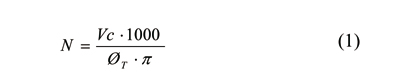
Where N (rpm) is the rotation speed of the milling cutter, Vc (m/min) is the speed of cutting and OT (mm) is the total diameter of the cutting tool.

Where Vf (mm/min) is the speed of progress in conventional milling, Zn is the number of edges of the tool used and fz (mm/rev) feed per tooth.
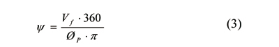
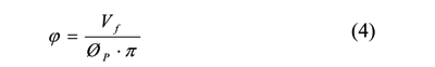
(degrees/min), is the speed of rotation of the workpiece and Op is the diameter of the workpiece. At the time of program operation, it may be more interesting have piece rotation speed in revolutions per minute, as expressed in the Ec (4).
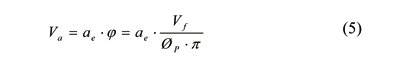
For the calculation of axial feed rate, it is necessary to determine what in milling is called depth of radial pass, ae (mm). In the EQ. (5) shows the expression for the calculation of axial feed rate.
2.1.2.2. In axis and tool compensation
The operation of lathe and milling orthogonal generated on the surface of the piece a characteristic Crescent-shaped, caused by the geometry of the tool used and the combined action of the rotation of the tool and cut the piece. In the forward axial direction, a geometric form peculiar, dependent is also generated in this case, the tool and geometry of the value of the compensation on the shaft and tool, which will be called Ew (mm). Extreme cases are reflected in Figure 4 and Figure 5.
One extreme case is when Ew = 0% Oef, being Oef (mm) the effective diameter of the cutting tool. This spatial positioning of the tool generates a convex surface in the machined part, as shown in Figure 4. The use of this position is recommended for finishing slots operations, to generate the agreement between the wall and the bottom of the Groove. The shape that is made the cut, is similar to an operation of turning ramping, where cutting inserts machined with the bottom, generating high axial forces.

Figure 4.Extreme case of cutting Ew = 0% Oef.
He gets when another extreme case Ew = 50% Oef. This spatial positioning of the tool generates a concave surface, Figure 5. This displacement prevents the effect of the cut in the bottom of the cutting edges, thus reducing the axial forces generated during machining. This positioning allows you to avoid the risk of causing interference between the center of the tool and the workpiece, regardless of the depth of pass (ap).

Figure 5.Extreme case of cutting Ew = 50% Oef.
2.2 Lathe-milling finishing with ball tip tool
Once rough piece gives complete, it is necessary to run the finished program to get the final part. In this case, applies a finish lathe-milling with ball-pointed tool. Machine tool users are continually under discussion between the need to maintain a high quality machining and the need to reduce machining time. A solution to these problems are machines equipped with two turrets. These machines allow a balanced machining, two tools are cutting at the same time.
Simultaneous cutting with two tools is faster, and at the same time balanced cutting forces counteract deformation which may cause one tool [6] pressure in thin pieces. Balanced machining has been historically used in the operations of turning, but recent developments in the machines and the like Esprit CAM software are expanding balanced operations machining technology of milling. Machining balanced on a lathe and milling machine may be better than a traditional machining for certain machining center.
The main of this type of simultaneous process advantages are faster cycles and balanced machining forces.
Faster cycles
When two tools machined the same geometry simultaneously with a tool above the axis of rotation and the other below, be duplicated material starting rate without affecting the tool. Another technique to use is to start machine with one of the tools and the second tool waits until the first has traveled a certain distance. The second tool is the first to perform machining at different depth, this mode can perform two operations in one pass.
Balanced machining forces
The bending occurs in slender or long workpieces are machined with a single tool is one of the problems facing this type of parts manufacturers. If applied at the same time machining with two tools there is a balance of forces which will reduce the risk of bending of the piece produced by machining with a single tool. The solution of the problem of bending of workpiece indirectly also reduces machining cycles to improve the quality of the piece.
Balanced finish
When balanced roughing is only used to generate milling passes, using passes of nibbling instead of finishing passes. Usually stops the time delay between the start of the first tool machining and the second to what they can do at different depth of pass. The first tool can complement the semi-finishing and the second until the final shape (Figure 6).
![Figure 6.Balanced finish [DP Technology ®]](https://img.interempresas.net/fotos/871884.JPEG "Figure 6.Balanced finish [DP Technology ®]")
Figure 6.Balanced finish [DP Technology ®]
Synchronize operations on the upper and lower turret
The timing of synchronized operations is vital since it avoids collisions and saves time thanks to actions such as the preparation of the tool to the next operation for a further optimization. You can drag an operation until the desired machining either before or after a change of tool.
Milling balanced
Balanced milling with a tool on the head of milling and other power in the lower turret tool allow to mechanize opposite sides of the workpiece at the same time. Balanced drilling and milling are more productive operations when the two turrets allow you move in and.
Milling balanced in 5-axis
This technology presents one of the biggest developments in the CAM programming because the top and bottom tools follow different trajectories of machining and must be carefully coordinated and synchronized to the Operations Manager so there is no collision. Balanced (Figure 7) 5-axis machining requires a multitasking with motorized axis B and a lower turret with tool machine. The use of two spindles is also recommended. Spindles have C-axis that provide movement piece.
This type of milling balanced is well suited to the manufacture of blades of turbines since you blades are some long, thin and prone to Flex. When the praise it is attached by two screws, spindles can grasp and apply torque on both ends of the workpiece. Since the piece is more rigidly tied it has less tendency to flectar. This configuration allows using spherical tools without tilting the nose of the tool. Is the orientation of the tool during the simultaneous 5-axis machining, machine can keep a constant cutting speed. This type of tooling is faster than a roughing and finishing. The simultaneous cut with two tools allows increase advance rates and maximize performance.

Figure 7.Balanced in 5-axis machining in a Mori Seiki milling.
2.3 Burnishing with ball
The machining of complex surfaces plays an important role in the process of introducing new products in the market. Wide variety of products, from dies for the automobile to the blades of the turbine industry, present complex surfaces. This type of surfaces tend to be machined on multi-spindle machines, making copying with spherical and subsequently polished tip strawberries when a good surface finish is required. The process of finishing and polishing by hand may represent more than 75% of the total machining time.
Among the different types of existing surface mechanical treatments, burnish with ball physicist - provides, in addition to an excellent surface finish, an improvement of properties mechanical component [7]. It's a simple, low-cost operation and which generates a high-quality final surface. In this sense, burnish with ball can replace finishing such as grinding, shot peening or grinding processes by hand. This process is of direct application in multitasking machines.
The process is based on provoking a small plastic deformation on the surface of the workpiece. This form will generate a bonded layer of metal that can reach thicknesses of between 2 to 10 µm. 'Crush' causes the following effects on the surface:
- Reduction of surface roughness by more than one order of magnitude. The finish is of the order of the Polish [8].
- Generation of residual stresses of compression on the surface of the piece, which is beneficial for the component fatigue behaviour. In addition, the absence of heat prevents metallurgical changes on the surface [9].
- Increase the surface hardness between 30-60% (HBN) on the basis of common steels, i.e. 180-250 HBN levels. In materials of high hardness, this increase is negligible.
The principle hydrostatic burnish by ball, illustrated in Figure 7, is based on the hydrostatic Pier. The normal force applied only depends on the pressure of the pump. The ball has a free movement of 6 mm which helps to absorb errors in parts and also facilitates the programming of the finishing process.
The application of this technique of burnished to the blade improves its roughness and increase resistance to fatigue of the piece.
 Principle of burnished hydrostatic with ball. (Right) Detail of the ceramic ball")
Figure 8.(Left.) Principle of burnished hydrostatic with ball. (Right) Detail of the ceramic ball.
2.4 Examples
In this example (table 1) the blade has been lathe-milling using the named capture tool clamping system. Then is the finishing operation of lathe - milling with ball tip. This operation is more durable than the rough. Finally, applies the polished technique to achieve a better surface finish and at the same time eliminate residual stresses.
The operations occur virtually to avoid possible collisions or unwanted movements that can cause errors.

Table 1.The blade manufacturing process.
2.5 Conclusions
The paper presents the implementation of a series of techniques for the manufacture of blades. It includes the application of lathe-milling for roughing, lathe-milling for finishing of the piece ball tip and polished.
2.6 Acknowledgements
The authors would like to thank for their support to the Department of universities, research and scientific policy of the Basque Government for its financing and to the Department of industry, innovation, trade and tourism of the Basque Government for its support via Etortek InProRet. The authors are also grateful to the UPV/EHU (UFI 11/29).
References
[1] H. Schulz, T. (1994) Kneisel Turn-milling of hardened steel and alternative to turning, CIRP, 43, 93-96.
[2] Ping Chen (1992), Cutting temperature and forces in machining of high performance materials with self-propelled rotary tool, JSME Int. J. SER., III, 35, 180-185.
[3] S.K. Choudhury, J.B. Bajpai (2005) Investigation in orthogonal turn-milling towards better surface finish, Journal of Materials Processing Technology, 487-493 170.
[4] V. Savas, C. Ozay (2008) The optimization of the surface roughness in the processof encased keep free turn-milling using genetic algorithm, Int J Adv Manuf Technol, 37, 335-340
[5] In a Pinch: Using 2 Tools to Balance Cutting Forces: www.dptechnology.com (2012).
[6] Golden P.J., Shepard, M.J. (2007) Life prediction of fretting fatigue with advanced surface treatments, Materials Science and Engineering, 15-22, 468-470.
[7] Lopez de Lacalle, L.N., Rodriguez, a., Lamikiz, a., Celaya, a., Alberdi, r. (2011) Five-axis Machining and Burnishing of Complex Parts for the improvement of surface roughness, Materials and Manufacturing Process, 26, 997-1003.
[8] Prevey, p., Ravindranath, r., Shepard, M., Gabb, T. (2003) Case Studies of Fatigue Life Improvement Using Low Plasticity Burnishing in Gas Turbine Engine Applications, Proceedings of ASME Turbo Expo, Atlanta, GA, 16-19.
[9] Rodriguez, a., López de Lacalle, L.N., Celaya, a., Lamikiz, a., Albizuri, j. (2012) Surface Improvement of Shafts by the Deep Ball-Burnishing Technique, Surface & Coatings Technology, 206, 2817-2824.