Online oil analysis responds to unexpected events and reduces maintenance costs
New sensor system for monitoring online of lubricant oil in gas turbine engine
Alberto Villar (avillar@TEKNIKER.es) and Marta Hernaiz, unit of chemistry of surfaces, Tekniker-IK4; Aitor Arnaiz and Susana Ferreiro, unit of intelligent information systems, Tekniker-IK4; Eneko Gorritxategi, Atten2 Advanced Monitoring Technologies: and Alberto Tellaeche, Autonomous and Intelligent Systems Unit, Tekniker-IK4.
22/07/2013Monitoring online of the quality of the lubricating oil in the gas turbines of the aircraft by means of a sensor system is already a reality. The main advantages of using a sensor online system are the access points of lubrication in extreme working conditions, the contribution of information on the behaviour of the different mechanical components of the system of lubrication and the possibility of implementing a plan of predictive and proactive maintenance for the detection of the early stages of degradation of lubricating oil. All are advantages result in significant savings in maintenance and operation costs.
Aircraft gas turbines can suffer serious mechanical failures caused by degradation or contamination of lubricating oil. Traditionally, oil control is carried out by means of periodic laboratory analysis, but through this type of analysis, it is not possible to detect the early stages of degradation of the lubricant and the time that it takes to receive laboratory results is often too long. Therefore, the analysis of the lubricating oil should be online, in order to respond to unexpected events and reduce costs of maintenance [1, 2].
The application of sensors online can be the solution of several unresolved issues in the aeronautical industry such as access to points of lubrication devices and engines working in extreme conditions, the detection of the early stages of degradation of the lubricant, provide information on the State of the mechanical components in the lubrication system and the establishment of a good system of predictive and proactive maintenance with the consequent saving in costs of maintenance [3].
The main objective of this work is to describe the process of manufacture and calibration of the sensors online Vis-NIR and OPD developed by Tekniker-IK4 and used in the monitoring of the State of degradation of the oil lubricant for aircraft gas turbines. These sensors have also been used in the monitoring of other types of lubricants and hydraulic fluids, such as Skydrol LD-4, which is a hydraulic fluid used in actuators for airplanes [4, 5]. The objective of these sensors is not having the same accuracy and precision of a laboratory equipment, but the development of a system sensor online with sufficient accuracy and precision to determine the quality of lubricant in order to decide whether the oil change is necessary. As a result, maintenance costs and the environmental impact due to unnecessary oil changes can be reduced.
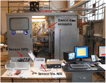
The sensors Vis-NIR and OPD have been testeados in the banks of proofs of the Free University of Brussels (ULB) and IK4-Tekniker during the different proofs realizar in the European project ELUBSYS, pertaining to the seventh program mark. The proofs in ULB have carried in conditions of pressesure and temperature comprised between 2-6 bars and 40-120°C and with a maximum flow of oil of 5500 l / h [4]. Instead the proofs in the bank of essays of IK4-Tekniker have been realizar to pressesures comprised between 2-7 bars and to 30°C of temperature since it was not possible to heat the oil in the interior of the bank of essays. The figure 1 sample the sensors Vis-NIR and OPD connected to the bank of essays of ULB [5].
Note that both sensors have been used in other applications as in the monitoring of the hydraulic fluid Skydrol LD4, used in actuators for airplanes. This work was done in collaboration with the Centre of aeronautical technology (CTA) from Vitoria in the framework of the project Airhem II (Etortek) funded by the Basque Government. In this project the OPD sensor has been used for the detection of particles and bubbles while the Vis-NIR sensor has been used in the monitoring of the viscosity and acidity of Skydrol LD-4 number [4].
Sensor visible - near infrared (Vis-Nir)
Vis-NIR sensor is a prototype used to monitor online content of oil additives Mobil Jet Oil II used as lubrication oil in aircraft gas turbines.
The sensor has an optical system that separates the do of light that crosses the sample of oil in different wavelengths obtaining the spectrum of transmittance of the sample. The components used for the development of the optical system of the sensor are the following: a light halógena white, a pinhole of 150 micras to direct the do of light that crosses the sample, a spherical mirror for colimar the light to the network of diffraction, a network of diffraction that separates the do of light in different wavelengths and a second spherical mirror that focaliza the light to the detector, which is an array of 128 pixels that works in the spectral rank comprised between the 400-1.100 nm, covering the visible rank (400-780 nm) and part of the infrared near (780-1.100 nm).
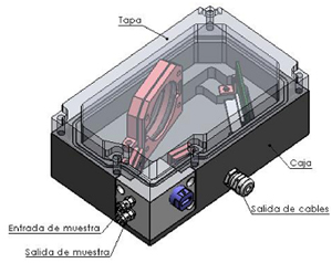
The mechanical design of the sensor has to ensure an easy mechanised of the pieces to a low cost of manufacture, as well as the robustness of the sensor. The components manufactured and assembled were were the housing, the accommodation of the optical components and the cell fluídica. The mechanical design of the housing and his different components has been realizar having in what the following considerations: precision in the position so much of the optical components as of the detector, simplicity of the setting, lightness and estanqueidad of the group. For the accommodation of the sample, the source of light and the filter of light has designed an independent body to the box, where go lodged all these elements, designated cell fluídica. In the cell fluídica the do of light crosses the sample, afterwards crosses the filter of light and finally goes through the pinhole, before incidir on the first of the spherical mirrors in the interior of the housing. The cell fluídica has been manufactured of aluminium and has an optical step of 1 mm. With the aim that once mounted all the group was the lightest possible, and at the same time was not difficult to manufacture and keep the necessary precisions have manufactured all the pieces in aluminium. To each piece has given him a treatment of anodizado in colour matt black with the end that if some ray of light diverts of the path wished do not reflect and incida on the detector. In the figure 2 shows an isometric sight of the design of the housing, whereas in the figure 3 shows a photography of the final setting of the different optical components in the interior of the housing. Regarding the conditions of work, the sensor can work to pressesures until 7 bars and 120 °C of temperature.
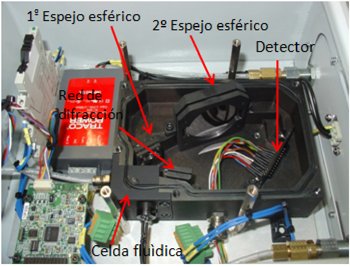
Calibration of the sensor has been carried out by means of multivariate data analysis applying different chemometric techniques, obtaining two models of calibration for the monitoring of the content of lubricating oil additives Mobil Jet Oil II. The first calibration model has been developed for the monitoring of the contents of additive understood range between 100 - 30% while the second model covers the range comprised between 100 - 70%. The first of the ranges has been selected in order to monitor the almost total oil degradation while the second range has been selected since aviation this kind oil usually changes when its contents of additive decreases up to a 80 - 70%. The spectra obtained with the sensor have been correlations with the contents of additive (RULER, ASTM-D 6810-2) of the specimens tested in the laboratory of industrial analysis of Iberian Wearcheck. So we have followed the following steps: pre-processing of obtained spectra, generation of model calibration and validation of the model. At the time of the pre-procesado have been tested different methods, from anti-aliasing of the Spectra up to methods to correct scattering effects. Calibration models were obtained by regression on minimum pictures partial or Partial Least Squares Regression (PLS). PLS is one of the most commonly used in multivariate data analysis linear regression techniques. A method that relates the variations in one or more variables (and variables) answer is treated with variation in multiple predictor variables (X-variables) [6]. Finally the validation of models calibration has been done through a cross-validation method known as leave-one-out cross validation. It is a method of validation based only on the data used for calibration by which so many Despliegue as samples are created there in the calibration, each time leaving a sample out for use in validation. The process is repeated until each sample used in the calibration has been left once outside to the validation. After all the residuals are combined to obtain an estimate of the error of the model prediction. All chemometric analysis was performed with The Unscrambler software see. 9.8 (Camo process AS, Oslo, Norway). Table 1 shows the results of calibration models developed for the monitoring of the content of oil additives lubricant Mobil Jet Oil II. While the results obtained during calibration are still satisfactory, it is necessary to improve the accuracy of the calibration models developed for the monitoring of the content of additives.
Results obtained during calibration of the Vis-NIR sensor
|
The model parameters |
Additive content: 100 - 40% |
Additive content: 100 - 70% |
|
Number of samples |
30 |
13 |
|
Main (PC) components |
6 |
3 |
|
Correlation |
0,962 |
0,879 |
|
SECV to |
4,809 |
4,827 |
aSECV: standard error of cross validation
Particle optical (OPD) detector
The OPD sensor sensor is a prototype whose functions are the detection and quantification of bubbles and metal particles and non-metallic in the lubricating oil. The sensor takes an image of the sample oil and using artificial intelligence that it has implemented is able to distinguish particles bubbles and make their classification according to their size. The sensor gives as a result a report in pdf format which shows an image of the sample oil with particles that are marked in red and green bubbles and the number of particles in three ranges: ≥ 4 μm, ≥ 6 μm and 14μm per ml of sample. Finally the number of particles is encoded by taking into account the ISO 4406 standard.
The OPD sensor Assembly consists of a filter of particles 190 microns that away from large particles that can clog a sensor component, a pressure switch (0-25 bar) which allows the entry of oil provided that the pressure in the system is less than 7 bars, a flow meter and a camera CMOS (Edmund EO 5012 C)a cell fluid illuminated by white leds and a data acquisition card. Figure 4 shows the different components of the OPD sensor.
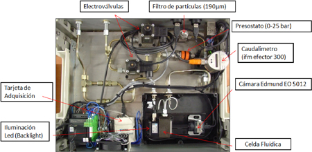
The fluidic cell is of stainless steel and has an optical step of 1 ml. The lighting of the oil sample is performed by a panel of white leds type backlight getting a completely uniform illumination of the sample. The lighting has been mounted independent of the fluidic cell in order to avoid high temperatures due to the flow of oil through the cell. The OPD sensor has a mode of automatic adjustment of the lighting, which is capable of adapting the camera exposure time to the absorbance of the oil, since not all oils absorb the same amount of light, being some darker than others. In terms of working conditions, the sensor that can withstand pressures up to 7 bar and 120 ° C temperature.
Calibration of the sensor OPD has consisted in the development of the algorithm for the detection and quantification of particles and bubbles in the oil lubricant Mobil Jet Oil II. Bubbles are identified according to their morphology, since they are more round than the particles and bodies for the hole or holes that possess in their interior. Particles are also identified on the basis of their morphology, being more amorphous than the bubbles and the size bodies, usually smaller than the bubbles. Calibration of the sensor has been performed in the trainer of IK4-tekniker to a temperature of 30° C and a pressure range of 2-7 bars. In the calibration have been used three types of particles: stainless steel (max. size = 45μm), iron (max. size = 60μm) and sand (max. size = 40μm). These particles have been mixed with the lubricating oil in the trainer in different concentrations. In addition during the calibration has been adding different amounts of oil lubricant degradation containing particles formed during the process of oil degradation. The algorithm has been developed with the software Falcon (MVtec Software GmbH, Germany). 5 Shown in Figure clearly the difference between the bubbles, round shape and with a hole in the Middle, and the particles that are small and elongated.
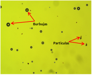
Image originally recorded by the camera with particles that are highlighted in red and green bubbles appears in the results report. Figure 6 shows the image recorded by OPD during calibration test bench of IK4-Tekniker at 30° C and 6 bar and the resulting image from the analysis to differentiate between particles and bubbles, in which bubbles to this image of the bubbles is noted in degree n and particles are listed in red.
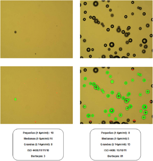
During the calibration process left different samples taken from oil of the Bank of tests to analyze the content of particles in the laboratory and thus be able to know if the algorithm performed the detection and quantification of the particles in the right way. The results show that overall sensor performs a correct detection and quantification of particles getting very close to the laboratory values. In terms of the content of bubbles, it was not possible to compare the results obtained with the sensor with no value of laboratory. Nevertheless, the results obtained in the calibration have been really satisfactory, it has been observed as the algorithm has problems to detect those bubbles that are on the edges of the image, since in some cases or not has detected them or mistaken for a large particle. On the other hand the rest of bubbles that appear in the image detects them without any problem.
Conclusions
The new sensors Vis-NIR and OPD developed by Tekniker-IK4 have shown that they can be a really useful tool in monitoring the State of degradation and pollution of oil lubricating aircraft gas turbines. The implementation of this type of system sensor on the plane would result in a significant reduction in maintenance cost and an increase in the safety of the aircraft to be able to make a diagnosis in time real turbine lubrication system.
While the results obtained during the calibration process with both sensors have been really satisfactory it is necessary to improve the calibration models and algorithms developed for Vis-NIR and OPD sensor respectively. In the case of the Vis-NIR sensor results were quite satisfactory though it is necessary to improve the accuracy of the calibration models developed for the monitoring of the content of additives. With respect to the OPD sensor results have shown that the algorithm performs a correct detection and quantification of particle while that is necessary to improve the detection of bubbles.
Once improved calibration models and algorithms the next step in the process of industrialization of the sensors would be the reduction in size and weight of both sensors, about all the OPD whose size and weight do not feasible that they may board the sensor inside a plane. It is also necessary that calibration models, algorithms and artificial intelligence are embedded in the electronics of sensors without the need to connect them to a PC.
References
[1] Schalcosky, D.C., and Byington, C.S., (2000). Advances in Real Time Oil Analysis. Practicing Oil Analysis Magazine, 11, pp.28-34.
[2] Gorritxategi, e., Arnáiz, e., Aranzabe, e., Aranzabe, a., Villar, a. (2009). On-line sensors for condition monitoring of lubricating oil. Proceedings of the 22nd International Congress on Condition Monitoring and Diagnostic Engineering Management COMADEM, San Sebastián, Spain.
[3] Halme, j., Gorritxategi, e., Bellew, j., in: Holmberg, k., Jantunen, e., Adgar, a., Mascolo, j., Arnaiz, a., Mekid, S. (Eds.). (2010). E-Maintenance, Springer-Verlag, London.
[4] A. Villar, A. Arnaiz, D. Otaduy, E. Gorritxategi, I. George, O. Berten. (2012). New on-line Sensors for Condition Monitoring of Lubricant and Hydraulic Fluids in Aeronautics. Proceedings of the International Congress on Lubrication, Maintenance and Tribotechnology LUBMAT'12, Bilbao, Spain.
[5] O. Berten, P. Hendrick, A. Villar, D. Seveno. (2012). Integration Of Oil Quality Monitoring Sensors Into A Test Bench For Aircraft Gas Turbine Engine Lubrication Systems. Proceedings of the International Congress on Lubrication, Maintenance and Tribotechnology LUBMAT'12, Bilbao, Spain.
[6] K. H. Esbensen. (2006). Multivariate Data Analysis in practice, 5th Edition.CAMO Software AS, Oslo, Norway.


