How aplanar the curve of discharge of a regulator of pressesure in applications of high discharge
Author: Michael D. Adkins, Swagelok Company. Translated by Juan Albiach,
The curve of discharge of a regulator of pressesure illustrates the rank of pressesures of exit (vertical axis) that the regulator will keep in front of different demands of discharge of the system (horizontal axis). Ideally, what want to is to operate the regulator in the flattest part (more horizontal) of the curve, that is where will keep relatively constant the pressesure even with significant changes in the discharge.
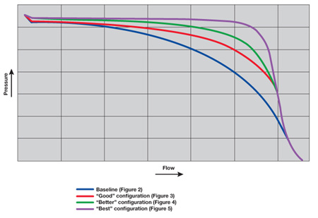
Unfortunately, the curve of discharge of a regulator of pressesure will experience always one some fall or inclination. The Figure 1 represents four curves of discharge, and when reading them of left to right, his slope downwards define it like ‘droop' or fall of pressesure. In the part more to the right of each curve can observe that there is a zone where the pressesure falls of form very rugged. The point in which the pressesure begins to fall quickly and until the pressesure approximates almost to zero, defines a zone called ‘choked – flow area' (area of sonic discharge). We have to avoid operate the regulator inside this zone because it does not comport of efficient form, generating us big falls of pressesure water down. If our conditions of service carry us to this zone of the curve, will have to consider the utilisation of another design of regulator or one of greater size.
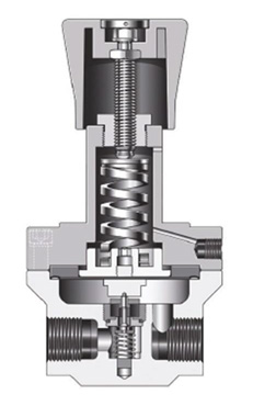
However, if we operate the regulator in the functional part of the curve (before the zone of sonic discharge), achieve to diminish the droop and a flatter curve for a wide rank of discharges, expanding like this the capacities of the regulator. Using a regulator of dock like starting point (figure 2), in this article will explore the following configurations:
- Regulatory piloted with pilot regulator (figure 3).
- Regulatory piloted with pilot regulator and external feedback waters down to the main regulator (figure 4).
- Regulatory piloted with pilot regulator and feedback to the pilot regulator (figure 5).
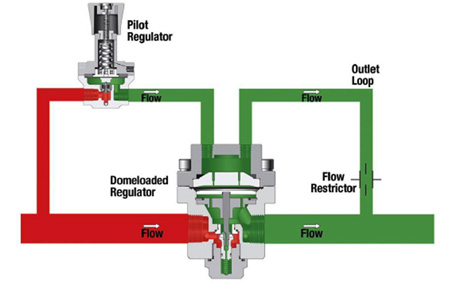
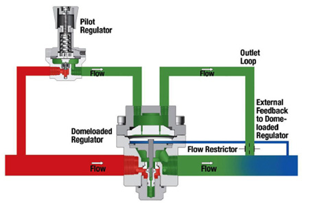
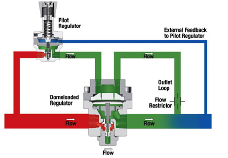
These configurations offer respectively a good, better and optimum performance when it treats to keep the pressesure of exit of a consistent form and therefore, offer curves of discharge progressively flatter for ranks of discharge wider.
Supposed
For this article, focalizaremos ours attention in a plant that has of an only point of supply of nitrogen for multiple processes. We will suppose also that these processes are not operating constantly, by what the demand of discharge will fluctuate along the day. If the plant had to employ a regulator of dock for this function, an increase of discharge would cause a fall of pressesure (droop) and by the contrary, a fall in the demand, would involve an increase or tip of pressesure. Both changes of pressesure will require frequent adjust manual of the regulator or additional regulators of point of use. In place of this, the plant can decide use a regulator piloted that allows a dynamic control of the pressesure without adjust manual, and will provide a pressesure of exit more stable in front of the variations of the demand of discharge.
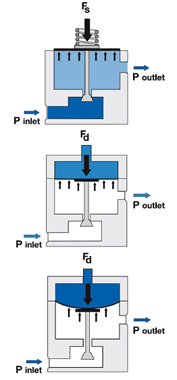
In a regulator piloted, the volume of gas to pressesure of the camera of pilotage substitutes the function of the dock of a regulator of dock (figure 6to). The camera presuriza slightly above the pressesure of exit required. This constant pressesure generates us a strength on the diaphragm. If this strength is upper to the created by the pressesure of exit in the inferior part, the obturador will open. When the pressesures equalise , the pressesure of exit creates a strength in the inferior part the diaphragm and the obturador closes (figure 6b and 6c).
The figure 1 sample the curves of discharge of the four regulators that can use in this application, all with pressesure of exit adjusted to 20bar (290psig). The first curve represents the regulator of dock like starting point of the comparison. The remaining curves represent three possibilities of use of the regulator piloted. As we will see, adding some external components and changes of inner design to the regulator piloted, will achieve an adjust dynamic of the pressesure of the camera of pilotage to improve the performance of the regulator.
Performance ‘well' - Regulatory piloted with pilot regulator
In this configuration employ a regulator piloted that answers to the fluctuations of pressesure allowing that the pressesure in the camera of pilotage keep constant for a wide rank of discharges of the system. This behaviour achieves adding a pilot regulator manager to control the pressesure of the camera of pilotage, as well as a bow of exit to allow the relief of the excesses of pressesure in the same (figure 3). This adjust allows a dynamic control of the pressesure of the camera that will help to keep consigns it initial of pressesure of exit.
The feeding of the pilot regulator realizar from the own line of nitrogen. Connecting the camera of pilotage with the exit through the line of purge, the inner pressesure will keep constant in 20bar. When the pressesure water down fall underneath of the 20bar, the pressesure of the camera also will fall but the pilot regulator will compensate it increasing the pressesure again until the 20bar of consign initial. By the contrary, if the pressesure water down increases, the regulator piloted will compensate it closing his orifice. This situation will involve an increase of the pressesure of the camera of pilotage, being then the regulator pilot the one who reduces his orifice and ventea the excess of pressesure of the camera of pilotage, to the main line waters down. These actions allow to both regulators go back to the pressesure of adjust initial.
The second curve of discharge of the figure 1 illustrates the improvement in behaviour of the regulator piloted more regulatory pilot in comparison with a regulator of dock. The dock adjusted of a regulator of dock, loses strength when it lengthens pushing the obturador to open the orifice. This situation causes a fall of the pressesure of exit (droop). With the dynamic control of the pressesure of the camera of pilotage that provides the pilot regulator, the zone of use of the curve of discharge grows in comparison with the regulator of dock. Depending on the specificity of the application, this configuration (of good performance) will be able to use in systems that experience increases of discharge without having to concern us of significant falls of pressesure. But, we can do it better.
Better ‘performance' - Regulatory piloted with feedback to the main regulator
In ours second better configuration will add a line of feedback to allow compensate to the regulator piloted the falls of pressesure water down. Using the same pilot regulator and bow of exit of the previous configuration, will incorporate a tube water down that it provides us feedback to the sensitive zone of the regulator piloted (figure 4). This configuration us aplanará the curve.
In the zone water down of our system, the pressesure will fall slightly afterwards that the fluid go out of the regulator piloted. For example, if the initial pressesure of exit is of 20bar, can be of 19bar to a small distance of the regulator. A line of feedback, located to short distance of the regulator (usually between 5 and 10 times the diameter of the tube of exit) will direct this low pressesure to the sensitive zone of the regulator piloted. Here, the diaphragm of the regulator detects the pressesure of 19bar and opens a bit more the obturador of the regulator to increase the pressesure of exit. Like result, the regulator answers dynamically and of form more precise that if we use an adjust static.
Looking the third curve of the figure 1, warn that it is flatter in this configuration. We remember that we are using the same regulator piloted with modifications in the sensitive zone, adjusted to the same pressesure of exit for the second, third and fourth curves. We can see also, that the operative discharge of the regulator before arriving to the zone of sonic discharge, has grown. However, still we can do it better.
Optimum performance - Regulatory piloted with feedback to the pilot regulator
The third configuration, ours better option, allows to the pilot regulator do adjust of pressesure highly precise in the camera of pilotage of the regulator piloted, according to the real pressesure waters down. Of the same form that in the previous configuration, this design uses a pilot regulator, a bow of exit to relieve the excess of pressesure of the camera and a line of external feedback. In this configuration, however, the line of tube of feedback carries us the signal directly to the pilot regulator (figure 5). With you adjust them realizar in the source of control of primary pressesure - the pilot regulator - this configuration keeps of form very precise the control of the pressesure water down and offers a curve of discharge very flat for a very wide rank of discharges.
Considering this example, the pressesure of exit for of the pilot regulator adjusts initially to 20bar, what wants to say that the pressesure of the camera of pilotage of the regulator piloted is slightly upper. Waters down of the regulator piloted, the pressesure falls until 19bar. This lower pressesure sends directly to the pilot regulator through the external line of feedback. Like answer, the pilot regulator increases the pressesure in the camera of pilotage of the regulator piloted, resulting the necessary correction of the pressesure of exit. Both regulators, the pilot and the piloted, adjust dynamically to allow that the pressesure in the bow of external feedback waters down keep in 20bar.
This configuration creates a bow that allows adjust constant and automatic to stabilise the system in the pressesure of consigns wished for an optimum performance. The results are evident in the fourth curve of discharge in the figure 1, which is very flat -without almost fallen of pressesure- for an extremely wide rank of discharges. This system will not experience sonic discharge until the discharges reach values very high.
The only way to achieve a curve of discharge even flatter -almost perfectly horizontal- is to replace the pilot regulator manual of this configuration by a pilot regulator controlled electronically. An electronic sensor connected to the regulator could do multiple adjust of pressesure by second offering a curve of discharge extremely flat. However, the electronic control is often no wished because of the need to feed it and considerations of hygiene. A system using a pilot regulator manual with feedback directly to the pilot regulator provides some very similar results without adding electronic components, cables neither sources of feeding.
How achieve a curve of discharge flatter
The applications of discharges elevated usually require the use of regulators with curves of discharge very flat, apt for a wide rank of discharges. Sometimes, a simple regulator piloted will contribute the parameters required for the application. However, it can be necessary add a variety of components to the system to expand the capacities of the regulator. The systems that provide pressesure of feedback water down to a pilot regulator waters up offer usually the best performance. It can not achieve an ideal curve of discharge perfectly flat for an infinite rank of discharges, but is well know that there are ways to improve the capacities of a regulator piloted, to achieve curves very flat for a wide rank of discharges.
References
For the fundamental in the interpretation and reading of the curves of discharge, see ‘Pressesure Regulator Selection Strategy. How to Use to Flow Curve to Ensure Effective Regulator Specification', Flow Control, August 2011.
About the author: Michael D. Adkins - Manager, Field Engineering and Pressesure regulators, Swagelok Company
Mike joined to Swagelok in 1994. In his current role supervises the team of engineers of field, engineers devoted to provide the direct technical support to the customers on the terrain. Also it directs the line of product of regulators of pressesure for Swagelok, where evaluates the needs of the market and develops strategies of product, positioning and price. Prior to this role, loaned his services like supervisor of development of new products, supervisor of control of quality, boss of project and engineer of manufacture.
Mike is graduate in engineering of mechanical technology by the University of Dayton and has a master in steering and administration of companies by John Carrol University.


