This news article was originally written in Spanish. It has been automatically translated for your convenience. Reasonable efforts have been made to provide an accurate translation, however, no automated translation is perfect nor is it intended to replace a human translator. The original article in Spanish can be viewed at El corte de chapa mediante oxicorte (2ª parte)
EQUIPMENT AND TECHNOLOGIES FOR CUTTING OF SHEET METAL
The cutting of sheet metal by means of flame cutting (part 2)
Rico, J.C. (1); Valiño, g. (1); Costs, e. (1); Villanueva, a. (2).
(1) Teachers in the Area of engineering of the processes of manufacture - Universidad de Oviedo
(2) Director of IDP, S.L.15/03/2002
4 PROBLEMS OF CUTTING OF SHEET METAL AND THE GENERATION OF TRAJECTORIES
Working with a CAD/CAM application destined to the automatic generation of trajectories of 2D Court for flame cutting machines requires inevitably meet all the specific problems posed by this process.
Although this knowledge focuses mainly on the problems that require the generation of trajectories, it inevitably leads often to deal with problems related to the geometry of departure, noting the added difficulty that involves generating a trajectory correct if the profile of the piece is not perfectly defined. A special type used in boiler geometry, as it is the case of those coming from the flat development of 3D pieces of sheet metal (hoppers, elbows, etc.), are also associated a specific treatment.
Other problems provided by the experience of users, and on technical topics such as control of the technological parameters (thickness, speed, etc.) of each process, the post-processing of CN programs and their corresponding transmission to the numerical control of machine, etc., also decisively influence the way in which the paths will be generated.
4.2 Problems relating to the geometry of starting
A first aspect that must be a CAD/CAM application for automatic cutting of sheet metal in 2D is "identification of the profile" of the piece to be cut, in order to ensure a proper generation of the corresponding paths. In this sense, it is essential to an automatic recognition of all entities that form the drawing selected in order to determine exactly which is the profile of the piece and failing, that errors presents. If an error is detected during this identification, the system must be able to correct it (to the extent possible) according to the user.
The geometry of starting in any CAD system may have been generated by the system itself or imported through standardized formats (DXF, IGES, etc.). When this geometry is done on the CAD system and focuses on the generation of trajectories of court in 2D, you must be a perfectly built flat profile. In many cases, this is not so and often the draughtsman or programmer mistakes inherent in their form of labour, not selected properly starting points or end of a segment to link it with the following, duplicate entities (one above the other)There are crosses of elements which must be consecutive, etc. Such problems need to be addressed if we want to avoid wrong paths, repeated cuts of a same segment/s, etc.
Other problems associated with geometry type consists of all those forks, areas of entities that overlap, etc., which are often produced during the manual layout due to the use of auxiliary elements, texts or benchmarks that have properly be deleted later, etc. The problems of this nature are not easy to detect, or even expand the work area. In the case of intersections and/or forks detection can be relatively simple, extending the drawing until the defect is visible. Probably a function of check at all the information associated to the plane or to tour the profile in search of badly closed elements, automatically can be very convenient is these cases.
If the profile of the piece to be cut is not correctly closed, that is, if the end point of an entity does not exactly match the start of the next, the path can simply not be generated by lack of continuity. If the distance of separation of the elements is large, of the order of the kerf or compensation of the tool (separation which depends on the type of torch, pressure of gas supplied, etc.), it is possible that geometry really have an end at the end. In the event that the separation distance is equal or a little more small bloodletting, the cut piece not will correspond to that actually has drawn, and when that separation distance is much more small (less than 1 mm) is likely to be of an undetected error for the user. In all these cases, it will be impossible to generate the desired full path.
The last of the cases mentioned above is a common problem when working with drawings generated with other CAD systems. Here the loss of precision in the decimal places associated with the points of the geometry that is to use standardized formats (DXF or IGES) can cause problems of very difficult to detect (even with successive enlargements) open contours at a glanceeven in the order of 10-12 mm, and therefore the inability to correctly generate the trajectories of court.
4.3 Special geometries of departure: developed surfaces for boilers
In the sectors of metal construction and above all boilermaking, appears a different kind of problems due to the common use of a special type of pieces. It's formed parts, whole or in part by developed sheet metal surfaces which in addition have intersections among themselves.
Flat development of these surfaces will have been doing traditionally manually, or by graphic methods of triangulation, using flexible templates, etc. Precision errors added by the difference in thickness of the manual layout joined due to rounding of decimals, etc. and when reading through the optical Copier of the cutting machine, result in an added difficulty to achieve the required dimensional toleranceeven when they are large (of the order of ± 1 or 2 mm).
For the classification of the developments usually employed in boiler works, often considered a number of elements, grouped by their form:
- Cylinders
- Cones
- Elbows
- Trousers
- Hoppers
- Transformers
In the same way the development of all intersections, cilindro-cilindro, cilindro-cono, cilindro-codo, cono-codo, etc. must be resolved
The parameters of the definition of each of the elements varies, even within the same group of classification. Among these parameters of definition is the number of divisions desired by the user for the development of non flat areas. Based on this number of divisions, will be in developing a greater or lesser precision contour lines that will define the piece in 3D. A large number of divisions may cause a program CN excessively long (each Division generated a line) and, depending on the process and the material, this precision may not be feasible (due to a too big drain, etc.).
Also the drawing of the development must include the possible lines of welding, in order to enable the Division of the piece in two or more parts when the size of the complete development exceeds the base plate. Welding lines have made to coincide well with the generatrices of lesser length of each development, or perpendicular lines on the edge of the piece. In this way, is achieved that the welding seams are as possible, allowing a saving in time, or facilitating its subsequent editing.
In the case of symmetrical elements, is should include the possibility of obtaining only a part of their development. The complete development can be built using the tools of the program based CAD/CAM.
4.4 Problem in the generation of trajectories
The requirements set out by the companies when it comes to proceed to generate the paths on a piece (drawing) can be grouped into several sections according to the considered cutting process, according to the thickness of the involved steel, depending on the type of CN (post-processor) and its memory capacity, etc. The study of the problem depending on the thickness of the steel as the most significant parameter was chosen in structuring this paragraph, given its greater relevance to the rest of factors.
4.4.1 Problematic in small thicknesses
Cutting sheets of small thickness, less than 3 mm, usually require best finishes. Implicitly, these small thicknesses are associated heat also affected children, and if the system used is by water or by laser cutting we can put in the order of the millimeter or the tenths of a millimeter with ease and with a good control of the cutting parameters. In the oxy-cutting or plasma we can Haz of 2 or 3 mm. But even so, there may be pieces of steel that require best finishes, not only in the thermal area but also in the roughness of the surface of the edges. A good finish of the parts (given a material and thickness), that it does not require subsequent deburring operations, must be controlled by the technological parameters of the process (pressure of O2, speeds, etc.), but we must not forget that the way to the careers of court will continue to play a very important role. Especially in two areas of the piece:
- Angled corners (with external angle > = 90 °), where the tool or torch passes through zero speed
- In areas or points of input/output (I/o) of the Court of the profile of the piece.
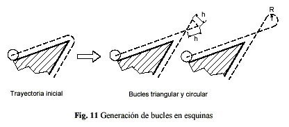
Steep corners the power, but programming it in post-processing (laser) or by manually controlling the pressure of the gas (plasma or oxy-cutting), so that the area close to the corner is not melted or "damaged" must be reduced. But often this energy reduction is not enough and requires significant experience of the programmer or operator in the technological aspects of the process, so it resorts to a solution of generating "security loops". These loops are used both in thin plate as of medium thickness (between 3 and 4.76 mm), with the purpose of improving the finish in these areas and even get the actual profile of the piece.
The loops obtain modifying the previously generated path (arch), so that it substitutes this by a bow (triangular or circulate) that goes out and goes in in shape tangential regarding the profile (figure 11). It avoids of this form that the speed of trip of the soplete do invalid (or diminish) in the near zones to the corners pronounced of the real profile, moving the changes of speed and steering to zones moved away of the profile.
With regard to the zones where produces the And/S of the cut, the form in that this realise , will determine the finishing. Like this for example, the perpendicular entrance and perpendicular exit to the profile, are used to to originate a "beak" or muesca undesirable on the piece and, depending of the process, this muesca can arrive to have an unacceptable size. When it programs one And/S with a true angle, diminishes the muesca, and can arrive to delete completely if it adopts one And/S tangential to the profile or causes a solapamiento (small zone by which happens twice). Whenever the profile have of a corner formed by straight stretches can initiate the cut in this corner so that it do not exist any muesca in the rest of the profile. All these appearances can observe in the figure 12.

Fig. 12 Programming of different types of entrances and exits on a profile
Therefore, in coding the trajectory, the possibility of making different types of entrances and exits to the profile should include. The types preferred by users are the entries and exits tangential (good finish) and entries and departures angle (the latter allowed when the control does not have entry to the Court by means of a curved section with compensation). It is important to also be able to schedule invalid output distances (Figure 12), to prevent reflux of gas (which is damaging the bottom of the sheet) to get the torch to a zone has no material (when it is finished the Court closing profile). This distance of zero output option is used in large thicknesses. Possible to generate an overlap of the entry and exit which ensures also the total detachment of the piece should also be.
The generation of trajectories of court should enable the creation of "bridges" between pieces in order that the profiles as well cut not prematurely emerge from the base plate and even to remain United once cut all the sheet metal. A solution of this type are usually highly recommended in the laser cutting of small thicknesses, avoiding that the tool can collide with any piece "ladeada" on the sheet, especially when interference sensors are not available (the remote control boquilla-chapa).
In the figure 13 can observe the two types of bridges but used: external bridges, generated between pieces to keep them joined between himself; and inner bridges, leaving small zones of the outline without cutting. The inner bridges diminish besides the loss of rigidity that produce the successive cuttings when the sheet is very thin (< 2 mm).

Fig. 13 Programming of inner and outer bridges

Fig. 14. Right choice from the point of entry and the sense of course to avoid distortions in the sheet
A final aspect that should be taken into account, caused by the fragility of the sheet that is accentuated to takes the Court, concerning also medium thickness plates (up to 5 or 6 mm). Paths should have the sense of course of the piece in such a way that the party where it is useless edge of the sheet, weak area, is cut in last place. This effect (Figure 14), can cause alabeos and deformations in the final pieces. It has been considered in the following section since that also occurs in medium thickness plates and is also preferred the grouping of the figures on the basis of the problem. In this case the solution will come given by the possibility of the change of direction of travel.
4.4.2 Problem in medium and large thicknesses
When working with sheet metal in large thicknesses and media (> 4.76 mm), the cost of the equipment is substantially increased. This requires to be even more careful because of the risk posed any waste of material. As it is clear from the technological aspects seen up to now, only the flame cutting and plasma (although also recently cut by water) allow the cutting of large thickness. The problems of loss of stiffness or movement of the pieces on the base plate have no meaning in this case, but the needs of programming of different types of I/o to the Court of the pieces are still validespecially to remove the output (by turning off the torch just at the end of the profile) preventing damage by reflux of gas.
Also should be envisaged for departures scheduled outside the profile to be up to the outer edge of the sheet. This course is intended to facilitate (even allowing in some cases) the extraction of the piece cut once. In this case, the problem occurs when it is cut very thick sheet (thickness of the order of 200 mm or more), since the transverse profile of court in this range of thicknesses turns out to be tapered and therefore prevents subsequent extraction of the piece. In Figure 15 can be seen as 3 different exits should be programmed to facilitate the extraction of the piece.

Fig. 15 Paths of court to draw the piece
Another aspect that occurs during the break for big thicknesses sheets, in this case than the 60 mm, is the need of high pressure of the gas in the flame (> 6 bar). This high pressure, necessary for the Court, produced a high number of Sparks with molten material landslides in the area where the Jet strikes the sheet to be cut. If this stream of sparks is directed against the operator, it will prevent their visibility and may not carry out an inspection "in situ", which sometimes is very necessary (for example, when performing a manual control of the speed of advance tickets or complicated profiles).
Additional reasons to control the direction of travel lies in that the remaining part should be, along the greater way possible, from the side where there is more material. If necessary change the point of entry, in accordance with that direction (Figure 16). This, together with the choice of that direction according to the quality of the cut, so that more perpendicular cut surface is on the side where it is the piece, (Figure 13), avoid unnecessary distortions due to global warming, in the absence of rigidity (in medium thickness plate)(, 3-5 mm), etc., that will produce inadequate dimensions. Therefore generation of trajectories of court programme should allow the change of direction of travel of the profile of the piece when it is necessary (Figure 14 and 16).

Fig. 16. Change of direction of travel to allow inspection of the work
Also in large thicknesses, it is necessary to carry out not only a preheating of the base plate, but also a previous drilling with the torch in the expected points of entry for Court (intermediate paths between displacement in vacuum and in court), allowing the subsequent entry to the profile of a stream of court in optimal conditions. The generation of trajectories of court must consider, not only schedule these previous drilling (areas of entry), but avoid the areas near these holes, which are areas that are very difficult to cut by have been hardened by temple (Figure 17 and 18).

Fig. 17. Programming of trajectories with the Court on previous drills home

Fig. 18. Detail of the entrance to the cutting area in
media and big thicknesses. The distance "a" is
produced in the sense of the trajectory and is in
According to the thickness.
media and big thicknesses. The distance "a" is
produced in the sense of the trajectory and is in
According to the thickness.
The use of material need becomes more patent in medium and large thicknesses. We can find a good example of this in the possibility of generating detached pieces or with one common side. For this reason, either on the same program of CN or on the pieces that are part of a base plate, generated some paths with compensation of specific tool (e.g., left) and other paths with other compensation (for example)(, or right with no compensation).
This peculiarity of change of compensation of tool within the same CN does not usually appear in commercial CAD/CAM programmes used in the cutting of sheet metal. On the other hand, inclusion for example, would cut parts attached (with one common side), with the resultant saving of material, time and cost associated with the Court (Figure 19).

Fig. 19 Trajectories for the cutting of detached pieces

Fig. 20 Preparation of chamfers or boards for welding

Fig. 21. Resulting profiles prepared for welding
When it comes to prepare the sheet for the Assembly and subsequent welding, are heads of court with torches rotated, and can also be mounted devices with double or triple torches. The programming of the order of (I, II and III) ignition in Figure 20 and the area where it begins and ends the chamfer, whether simple chamfer (Union v), double (X Union or and), or triple (Union K), it must be taken into account in the generation of trajectories, in such a way that the postprocessing can recognize the lines that should be applied the / the chamfers. This allows to leave the piece prepared for any type of welding, in curved profiles as a straight (Figure 21).
4.5. Problems in programming. Numerical controls and post-processors
Apart from the problems already mentioned, there is another problem associated with the sheet that is practically independent of thickness. These problems are due to the process itself and affect the form of programming, to the positioning of the sheet to the particularities of the CN and post-processor, etc.
To this respecto fits to quote that the edges of the sheet do not are used to to form part of the pieces, because of his oxidation and to the bad finishing that present. In some cases as in the oxicorte, this exigencia stresses even more because of the backflow of gases, on the inferior part of the sheet, when going in to cut the material. In sheet of little thickness, can go in to cut the material from the outside, but the adjacent zone, of some 5 or 10 mm of "margin", can not belong to the piece (distances Xmin and Ymin in the figure 22). It prefers even go in to cut from the interior of the sheet, giving by lost this small zone of margin.

Fig. 22. Significant points to programming CN
The positioning of the base plate on the table (point of overlap), the origin coordinates (0,0) and the programme (initial situation of the torch) should be perfectly controlled by the system. The operator must have knowledge of all these aspects and if possible, work together with the programmer when prefixed them.
In this same vein, the initial functions of the program take care of these tasks, should enable full mobility of the sheet, using the point of interweaving (inferior-izquierdo vertex of the sheet), which shall cover the origin of coordinates (0,0 of the CAD/CAM program) and the origin of programme (0,0 of the CN).
The purpose of the modification to will of the distance from the origin of coordinates to the vertex of the sheet, lies not only in knowing exactly where the torch must position itself to restart again the Court after a forced stop, shavings or strange in the guides elements)(, etc.) otherwise it would cause the mess of the sheet, but also because usually this origin point serves to make reference in the case of the use of solidarity torches, measuring about him the distances which are posicionarán other nozzles (Figure 22). The developed program automatically calculates the point which will serve as origin of coordinates (by placing at the intersection of the horizontal and vertical tangents to the outer parts) and positioned the point of interweaving of the sheet to the distance from (Xmin) security(, Ymin). In this way, any profile is approaching more than what is allowed on the edge of the sheet.
Before the process of generation of trajectories, the user must have specific functions for the correct positioning (manual or automatic) profiles of the / s piece/s on the base plate, which together with the possibility to set and/or modify the point of overlap on the drawing sheetthey will lead to the correct selection of the origin of programme and other significant points.

Fig. 23 Safety distances on the edge of the sheet and path of output for a cut
It is also interesting to have the possibility of cutting paths that do not require any prior geometry drawn. This option has multiple applications, the most usual is to include, in the same CN program, a last trajectory of Court intended to generate a particular Trim excess of the base plate (Figure 23) with a generally rectangular in shape, to facilitate their subsequent storage and reuse.


")


")