This news article was originally written in Spanish. It has been automatically translated for your convenience. Reasonable efforts have been made to provide an accurate translation, however, no automated translation is perfect nor is it intended to replace a human translator. The original article in Spanish can be viewed at El corte de chapa mediante oxicorte (1ª parte)
EQUIPMENT AND TECHNOLOGIES FOR CUTTING OF SHEET METAL
The cutting of sheet metal by means of flame cutting (part 1)
Rico, J.C. (1); Valiño, g. (1); Costs, e. (1); Villanueva, a. (2).
(1) Faculty of engineering of the processes of manufacture - Universidad de Oviedo
(2) Director of IDP, S.L.15/03/2002
(1) Faculty of engineering of the processes of manufacture - Universidad de Oviedo
(2) Director of IDP, S.L.15/03/2002
1. INTRODUCTION
Among those non-conventional processes whose scope is mainly of sheet metal cutting, you can make a particular classification leads to encompass many of them (90 per cent of industrial applications) in a group only called cutting Jet (beam cutting processes). In these processes, the tool is located in perpendicular direction to the surface of the sheet. The Jet strikes in this direction and cut sheet. The nature of the Jet determines a second classification of the different processes of court-Jet:
Those processes that use direct mechanical action, either of a single material or combining it with abrasives, to influence on the material to be cut, cutting are called waterjet mechanical (mechanical beam processes). They are used when traditional techniques due to the hardness of the material, may not be used to its extreme fragility or, mainly, when they can be damaged if they machining by electrical or thermal processes (sensitivity to high temperatures). Include, in the proceedings of this nature, the Court with or without abrasive waterjet (waterjet machining, WJM and abrasive waterjet machining, AWJM) and the air with abrasive jet cutting (abrasive jet machining, AJM).
When the separation of the material is mainly due to the effect of high temperatures located on a small area of material, we have thermal cutting processes by Jet. They have a wide field of application, and occupy a growing market segment. This is due in part, not only to the increase in the number of machines, but also to the diversity of energy sources used to cause the localized heat increase. Flame cutting (flame or oxygen-flame cutting), the arc of plasma (plasma arc system) and the laser (laser beam cutting) are the main processes applicable to the sheet. The cutting beam of electrons (electron beam cutting) also belongs to this type of processes, but is not suitable for cutting sheet 2D, but rather for precision machining in the drilling of small holes, engraving, heat treatments, etc.
A critical parameter that present all these processes around the cutting line is the affected area thermally (ZAT) around the demarcation line. There are currently works to reduce the area, not only controlling the cutting parameters but improving and/or testing new technologies. In the laser cutting wide areas are significantly reduced Haz with processes such as plasma or oxy-cutting (1-4 mm), reaching under optimal conditions and using processes such as the laser, values of 0.1 mm. The decline of the Haz, in certain thermal processes, is in the possibility of cutting sensitive materials to heat such as plastics, fabrics, etc. significantly increasing its field of application.
2. CUTTING OF SHEET METAL BY OXYFUEL TECHNOLOGY
2.1. The process
The process was developed completely in the 20th century and its first applications were carried out in Europe. However, its total development to what we know today by oxy-cutting occurred in United States during the first quarter of the 20th century.
The process of flame cutting, contrary to what may seem, does not consist of a fusion of metal, the Court is produced by a literal combustion of the same. In other words the cut we burn the metal as we move forward with the torch. For this reason, the presence of alloys becomes critical, since they reduce the capacity of the steel to be burned.
So that there is a reaction of combustion are necessary three requirements; presence of fuel (to its ignition temperature), the presence of oxidant (at a minimum proportion), and an initiator agent. In the process of flame cutting, fuel the faith, the oxidant is the O2, and the initiator agent the flame of the torch. Under normal conditions, even if we apply an initiator agent to a piece of steel, it does not Burns spontaneously for two reasons; the faith content is not to their ignition (approximately 870 ° C) temperature and atmospheric O2 is not pure enough (the atmospheric O2 is located in a proportion of 20 per cent and the minimum proportion needed to burn the faith is 87%).
2.2. The torch
The cutting torch plays three different roles: bring the content in steel Fe to its ignition temperature, provide a surround atmosphere with a higher share than the minimum necessary in O2 and, finally, generate the initiator agent.
For the first thing the torch of court uses part of available O2 for mixed with the fuel gas to create the pre-heating flame formed by a ring of flames in the cutting nozzle. The flame of preheating can reach temperatures between 2,425 and 3.320 ° C depending on the type of gas used and the wealth of O2 in the mix. The ratio of O2 to gas in the mixture for the preheating is controlled by the two valves that incorporates the torch. With the flame of preheating well adjusted, approaching it the piece cut until you reach the ignition temperature. Once you reach it, the metal becomes a brilliant orange color and you can see some sparks jump from the surface.
")
Fig. 1. Four torches work simultaneously
on the same sheet (ARGON)
on the same sheet (ARGON)
At this time should be operated the lever of the torch to allow the output through the central hole in the mouthpiece of a jet of pure O2 (called Court-Jet) (Figure 1). He is thus manages to enrich the atmosphere that surrounds the prewarmed piece to make possible the combustion in O2.
Immediately, and the presence of preheating flame also acts as initiator agent, starts the exothermic reaction of combustion of the faith, which will lead us finally to the Court of the piece. As all combustion, oxidation of the faith reaction is highly exothermic, and precisely that enormous amount of energy detached reaction helps bring the areas adjacent to the ignition temperature, and thus progress in the action of the Court.
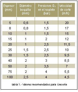
Oxide resulting from the combustion flows constantly through the slot, whose walls heats spreading the combustion reaction. To get clean and economic courts, it is convenient to not use too high pressures of O2. Often manufacturers of flame cutting machines provide technological tables with the most recommended values of pressure, speed cutting, etc. depending on the thickness of the material to be cut (table 1).
In some cases, the tables include data relating to the indentation of the Court (table 2) depending on the pressure (proportional to the thickness), and type of torch used (for chamfers, of type double or triple, etc.). Other tables provide data for the consumption of different gases used for the purpose of determining the cost of court operations.
")
Table 2-recommended values for the process of flame cutting (SAF)
2.3. The combustion of the faith
In the combustion of the faith, there are the following chemical reactions matches estequiométricamente:
1ª reaction:
2 Faith + Or2 3v4 or 2 UGLY + 128 kcal
2ª reaction:
3 Faith + 2 Or2 3v4 or Faith3Or4 + 268 kcal
3ª reaction:
4 Faith + 3 Or2 3v4 or 2 Faith2Or3 + 394 kcal
2 Faith + Or2 3v4 or 2 UGLY + 128 kcal
2ª reaction:
3 Faith + 2 Or2 3v4 or Faith3Or4 + 268 kcal
3ª reaction:
4 Faith + 3 Or2 3v4 or 2 Faith2Or3 + 394 kcal
To be able to compare the three reactions, must take rates of heat released per kilogram of faith, which are respectively: 1,142 kcal, 1,598 kcal and 1.762 kcal. Although the third equation is the most exothermic, and therefore appears to be more spontaneous (theoretically, it is) in practice is not the predominant reaction since the amount of O2 needed to burn 1 kg of faith following each of the reactions is respectively: 267, 200 and 300 l. Therefore, the practice shows that while the third reaction only occurs in the oxy-cutting of major sections (where applicable an abundant stream of O2's Court), the first and second are much more common.
The faith is being oxidized and its corresponding oxides are formed, they, and part of the faith of the piece, are fused by thermal action game and are being pushed out by the physical action of the stream of O2. The property of the oxides of Fe melt at temperatures similar to the Atomic faith makes possible the phenomenon of the flame cutting. This property is exceptional, since most of the metals melt at temperatures lower than their oxides. Precisely for this reason metal such as Al, Mg or Cr can not be cut by this process its oxides melt at a temperature much higher than its atomic phase.
It is thus that the fundamental application of oxicorte, and for which is designed, is the cut of steels of low content in Carbon (usually between 0,1% and 0,3%) and low content in aleantes. The presence in high concentrations of the aleantes usually present in the steel affects to the capacity of the process to cut the metal. Elements like the Mn, If, P and S, affect little to this capacity when they are presents in normal concentrations. On the other hand, elements like the Cr, Neither, Mo, and of course the C, reduce the capacity of cutting of the Or2 existing some limits from which the cut is not possible: 5% for the Cr, 7% for the Neither, etc.
Before attempting to cut a sheet by flame cutting, must be taken into account the elements contained in the material, their combinations, alloys exactly equal to as it should be done before applying heat treatment or a hardening to the flame. All the metals must be examined, not only from the point of view of the alloys that contain, but also of the properties that the combinations these alloys have.
2.4 The preheating
The main function for pre-heating flame is bringing the piece to the ignition temperature, as mentioned above is of approximately 870 ° C. However, the flame of preheating has other functions:
- Clean the surface of the piece to cut of any odd substance like oxide, dirt, flakes, no only during the precalentamiento but also during the action of cut
- Help to reach the temperature of ignición to measure that advances with the cut.
- Keep some surroundings of protection around the chorro of Or2 of cutting.
- Precalentar the Or2 content in the chorro of cutting doing it more reactive.
- Help to keep the slags produced in the slot of the cut in fluent state so that they can be expelled.
2.5 The Court O2 Jet
As explained above, it is obvious that the O2's Court plays a leading role during the cutting operation. Its purity must be of 99.5% or higher. Purity of a 1% loss means a loss of speed of approximately 25% and in turn increases the consumption of O2 by approximately 25%. With a purity from 95% O2 oxidation cutting action is impossible to achieve and is transformed into a merger and cleaning action.
To get the best quality in the Court, always be observed the recommendations of the manufacturer of the referring court teams a:
- Size of the filter in function of the thickness of sheet to cut.
- Adjust of the flame of precalentamiento.
- Pressesure of gas.
- Pressesure of Or2 of cutting.
- Speed of cutting. If they follow properly the recommendations will achieve a suitable cut in which we will be able to observe the following characteristic (see section 3)
- Faces of perpendicular cutting with some soft waters
- Absence of bites
- upper Singing anguloso, neither rounded neither melted.
- inferior Singing free of slags and rebabas.
There are many applications of flame cutting in which does not require these levels of quality and are normally accepted more bastos cuts. This is the more general case in which the surface of the cut will be covered with welding, hidden within the piece to be manufactured or covered with paint. If the quality that is required to cut not is the maximum, the speed of progress may be, in many cases, increased.
2.6. Flame cutting machines
Flame cutting machine consists of a gantry on which is mounted the torch, so their travel speed is constant and keeps invariably to the height and tilt right, essential conditions for economic and clean cuts. Pressures of all gases are usually also controlled. Most of the machine tool of this type include the possibility of also using torches of plasma, which are mounted on the porch in the same way that the oxy-cutting, but by coupling them to different gases required by plasma now.
. Detail of the portico with several torches")
Fig. 2. Machine for flame cutting (Oxiser). Detail of the portico with several torches
There are many models of flame cutting machines, from the portable machine, which builds and moves on the sheet, to the fixed machine (Figure 2), with one or more heads of court, capable of cutting plates of different thicknesses. Still today, it is usual to see machines that use a device of reading or copying optician who is following the contour of the / s piece/s to cut drawn on a plane set on a table joined to the machine. However, each day is more common the incorporation of the flame cutting machine numerical control (CN), so that the geometry and the technological parameters are introduced in the CN in the form of a coded program. The installation of a flame cutting machine, still equipped with numerical control, is not very expensive if compared to any other machine tool.
With the use of the optical copying both the CN, the oxyfuel allows all kinds of straight and curved cuts on any thickness steel sheets or profiles, tubes, etc. They can be cut off in good plates overlapping, even very thin, if they are well against each other. When the torch is properly regulated (pressure, mixing and appropriate speeds), the courts are uniform and look good; just a simple and subsequent trimming to obtain an acceptable finish. Although it depends on the application, are often left the edges as remain after cutting.
3. CONTROL OF THE TECHNOLOGICAL PARAMETERS. QUALITY OF THE CUT
Waterjet cutting processes are similar to what happens in other processes such as machining removal of material, some critical technological parameters that are needed to control in order to obtain the required dimensional tolerances and surface finishes. For the less widespread as the laser and cutting by water processes, can be said that she is still still tested new combinations of technology based on those materials parameters (either new or improved) likely to be cut by these methods.
As regards the flame cutting and plasma cutting, suitable for the majority of construction steels, cast steel and alloy steel (including stainless steel), are relatively simple processes with few variables to control. Despite this, the number of companies that really optimize those few variables (technological parameters) is very low, creating a false idea that are processes where you can not get good finishes or much less small tolerances (in the order of 1 mm).
Dimensional inaccuracies can be caused by wrong cut paths, movements of the plate or parts during cutting or residual stresses in the plate. Defects that can be corrected during the programming of the CN, using suitable for example paths by inserting bridges in the profiles of the pieces during the break, by controlling the direction of travel (figura3), etc., will be treated in the following section. In other cases are used outside of programming techniques, making the cooling of the Haz cold immediately after cutting air utilization of plasma in tables of water, control pressures and flow rates of the gases when the sheet still residual stresses,, etc.

Fig. 3 Influence of the sense of journey of the paths in the quality of the Court
All the problems and defects which are cited below, including its causes and possible solutions, have been prepared not only thanks to the existing literature, but also taking into account the experience of users and, above all, manufacturers of plasma and oxy-cutting machines.
The quality of the surface of the cut for the manufacture of metal structures is recommended as the standard DIN 2310, and recently, by the European draft standard EN 1090-1-1993. Figure 4 shows a part of this standard, corresponding to the finish of the cut, which is indicated as the angular deviation of the surface of Court (in the direction of the Jet) must be controlled and depth of stretch marks or marks within the meaning of route (direction of advance of the Court). The standard also establishes that both requirements can soften if plates or structural components are to be welded on the surface of the Court.

Fig. 4. Detail of the European standard EN 1090-1-1993 relating to the finish
surfaces of cut for steel structures
surfaces of cut for steel structures
Various errors observed for technological reasons, can be classified according to the damage or defect caused the sheet. This classification is established in order to recognize their causes and enable his subsequent remedy. It should be noted that errors are individual rate, i.e., primarily due to a single parameter, but the combination of several of them can give rise to contradictions in the forecasts of the causes which gave rise to them. It should also be noted that for the elaboration of the defects here listings not have taken into account causes external to the process, such as vibrations from the machine or other future machines in the workshop, etc. Also assume that the O2 used is industrial standard purity.
3.1 Defects on the upper edge of the Court
- Fusion of the corners. The edge of the cut, presents a round excessive because of the fusion of the material in said zone. This defect has to mainly to a speed of cutting too low or to a flame of cutting (pressesure of Or2) too strong. Also it can be due to a distance filter-sheet too big or too small or to a mix with too much Or2 (figure 5to)
- Learning of chain of drops melted. The chain of drops melted of the figure 5b, formed on the edge of cut are been due to dirt, oxides, etc. existent in the surface of the sheet. In second order of magnitude can be due to an excessively small distance between filter-sheet.
- Edge of cut colgante. The learning of an edge of cut colgante, with convex form on the ideal edge (to square), is due to a too strong flame. Still when the pressesure and mix of Or2 is correct can produce this defect if the distance between filter and sheet is small or the speed of cut is excessively slow (figure 5c).
- separate Edge of the zone of cut with adherencia of slags. In the figure 5d can observe this error caused generally by a distance of the filter to the too big sheet. When the distance is the correct, can produce by a pressesure of the Or2 of cutting too high.
")
Fig. 5 Defects of the upper edge of the cut profile (Messer)
3.2 Defects on the surface of the cut: irregularities
All deviations and irregularities of the ideal cut surface are defined according to the distance between two parallel planes, the indentation-delimited and created by contact between the flame and the points top and bottom of the sheet on the profile of court. Theoretically, the correct angle of the plate with the sliced surface must be 90 °, so that the indentation must remain constant throughout the entire thickness of the steel.
- Concavity under the upper edge. The concavity that produces in the immediately inferior part to the upper edge of the surface of cutting is due to a pressesure of Or2 too high, that produces a chorro turbulent initially, going back laminar when penetrating in the sheet. This type of damages reveals also dirts in the filter (figure 6to).
- Narrowing of the edge (convergent bloodletting). This defect produces when both surfaces of cutting (right and left), converge to the inferior part. Clearly it indicates a chorro of feeble cutting that can be been due to a too high speed, high distance of the filter or to the employment of a filter of diameter too small for the thickness of the sheet that wants to cut (figure 6b).
- Broadening of the edge (divergent bloodletting). It is the contrary defect to the previous, consider also the opposite causes (figure 6c).
- concave Section of the surface of the cut. The concavity produces along all the surface, particularly in the half zone (figure 6d). It produces mainly by a speed of cutting too high or for using little pressesure of Or2. Other secondary causes are been due to the filter, small diameter for the thickness considered, dirt or deterioration, etc.
- Section ondulada of the surface of the cut. The transversal section of cut presents in this case some concave and convex inflections alternated (figure 6and). As in the majority of these defects, the high speed of cut is the paramount cause. In this case, the employment of filters too big or his vibration (caused by dirt along the guide, etc.) can also originate these ondulaciones.
- Surface of cut diverted of the vertical. If the surfaces are parallel, without defects in his interior, have to presuppose that the pressesure, speed, and distance of the filter are correct. Therefore, this defect only can be been due to a wrong angular positioning of the antorcha. Occasionally it can produce by superficial defects or dirt in the sheet (figure 6f).
- inferior Edge rounded. In the figure 6g observes this defect, being able to be more or less severe in function of some damages suffered by the filter. Also it can produce when the speed of cut is very high (flow very turbulent of the flame)
- Stair in the inferior edge. It treats of a similar defect to the previous. The causes are also the same although predominating the excess of speed (figure 6h)
- defective Steering of the cut and transversal surface ondulada. The surface of cutting does not follow a straight line, but it presents an outline ondulado (figure 6i). This irregularity in the steering of the cut has to mainly to the excess of speed or to the high content of the aleantes. Secondary causes can be the dirt or damages in the filter, contained in high Carbon or flame with excess of gas comburente. If the control of the speed does of irregular form also self-evident of this form.
")
Fig. 6 Defects on the surface of the cut piece: irregularities (Messer)
3.3 Defects on the surface of the cut: marked
The separation and direction of the lines of markup, form a pattern that reveals how the process is underway. Standards DIN 2310 and in 1090-1-993, details which must be the ideal marking pattern and how deeply can have trademarks. The ideal pattern must have brands forming right angle with the upper edge of the Court and a small deviation to the rear in the direction of the March, with the bottom edge. Any deviation, both in the direction of the lines marked how in depth, includes a misuse of any of the parameters.
- Excessive deflexión of the marked inferior. It is a very usual defect in this type of processes and perhaps the less important. The excessive speed of cut is the main cause. When the exigencias of finishing are not very severe, is preferable to use a high speed of cutting still when the marks present said deflexión (figure 7to).
- Marked upper with deflexión. The upper pattern finds moved to the rear part. It is due to a wrong angle of the antorcha in the steering of the cut. (Figure 7b).
- Excessive deflexión of the marked inferior to forward. Usually it indicates that there is a defect in the filter that produces a flow of the very turbulent flame (figure 7c).
- Deflexiones local of the pattern of marked. The irregularities of the marks of the pattern that manifest by deflexiones in one or another sense (to forward or to backwards) like the ones of the figure 7d, are caused by lines of segregation, inclusions distributed (of zones with distinct concentration of aleantes), inclusions of slag and other similar defects on the sheet.
- Depth of the marked excessive. When in transversal sense to the cut, the depth of the marks is excessive, and independently of the pattern of marked that remain recorded on the surface, this indicates that the speed of trip of the antorcha is too high or irregular. Also it can be due to a too short distance between filter-sheet (figure 7and). Irregularities in the depth of the marked. The differences regarding the depths of marked, happening from a marked normal to the of the previous case and vice versa (figure 7f), put of self-evident that has produced irregularity or excess in the speed of cutting.
")
Fig. 7. Defects on the surface of the cut: dial (Messer)
3.4 Defects on the surface of the cut: incomplete cuts
They are defects characterized by loss of continuity of the Court, causing defects of separation, total or partial, of court surfaces.
- isolated Zones of cut interrupted. In the figure 8to, can observe a defect of this type, that self-evident by the apparition of a triangle of remanent material, no cut, in the inferior part. As it is to expect, is due to a speed of excessive cutting or to a too feeble flame that no traspasa all the thickness of the sheet.
- Groups of zones of cut interrupted. When it produces the same previous defect, but this time in shape of isolated and irregular groups distributed along a zone, means no only that the speed is too high (flame too feeble) but besides there are zones oxidadas, slag, etc. in the surface of the sheet (figure 8b).
- Zones eroded in the inferior part. This phenomenon, characterised by big zones eroded, during irregular intervals, situated in the inferior part (figure 8c), is an usual consequence of the employment of a speed of cutting excessively slow.
")
Fig. 8 Defects on the surface of Court: courts Incompletos (Messer)
3.5 Defects by accession of slag
Deposits of slag in the lower or central part of the surface of the Court are very damaging flaw for the post process can only be removed with difficulty.
- Bars of slag adhered in the inferior part. The learning of a "chain" of slag in the inferior edge of the surface of cutting (figure 9to) can be due to values excessively basses of the speed, although the most usual cause consists in the employment of filters too small for the thickness. Other secondary causes are, a too strong flame, or a flame with high content of gas comburente
- Zones of slag incrustada in the surface of cutting. The defect that observes in the Figure 9b, is due to a content in aleantes too high. 3.6. Defects of agrietamiento The cracks can appear inside or on the surface of cutting and are atribuibles to the material. The visible cracks (on the surface) are much more frequent that the interns.
- Cracks in the surface of cutting. The cracks that schematise in the figure 10to, always visible externamente, produce by content in carbon or in aleantes too high, susceptible steel to thermal sensors break, insufficient thermal sensors treatment of the piece, cooling too fast, etc.
- internal Cracks in the vicinities to the surface of cutting. The cracks appear inside the sheet, in near zones to the surface of cut, only are visible in a transversal section (figure 10b). The causes are analogous to the ones of the previous case.
")
Fig. 9 Defects by accession of slag (Messer)
")
Fig. 10. Defects of cracking (Messer)
Normally manufacturers of machines, numerical controls and even suppliers of gases, produce tables that summarize the causes and the most common defects. Sometimes, these tables of "practical advice" come to establish causes of different order of magnitude for one type of failure, becoming genuine user manuals.
All the problems mentioned so far are related to technological parameters not involving directly the generation of trajectories. With numeric controls that allow you to program the cutting speed, the pressure of the gases, and even the distance from the mouthpiece to the sheet (distance with transducer control system), are solved easily and will pose any difficulty at the time of the automatic programming using a CAD/CAM system.
However, the problems that arise in the next chapter does require a specific programming, and currently can only be tackled successfully when you have a system very specialized CAM.


")

")